Device and method for identifying, calculating and detecting vacuum of condenser of power plant
A detection device and condenser technology, applied in vacuum gauges, measuring devices, measuring fluid pressure through electromagnetic components, etc., to achieve the effect of increasing the measuring range and improving the accuracy
- Summary
- Abstract
- Description
- Claims
- Application Information
AI Technical Summary
Problems solved by technology
Method used
Image

Examples
Embodiment 1
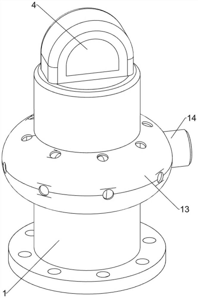
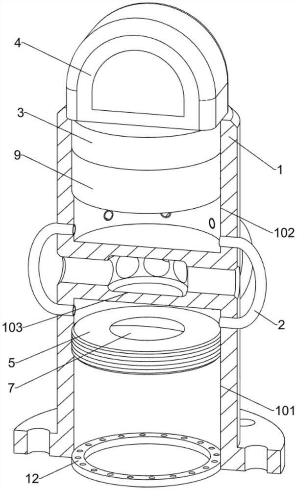
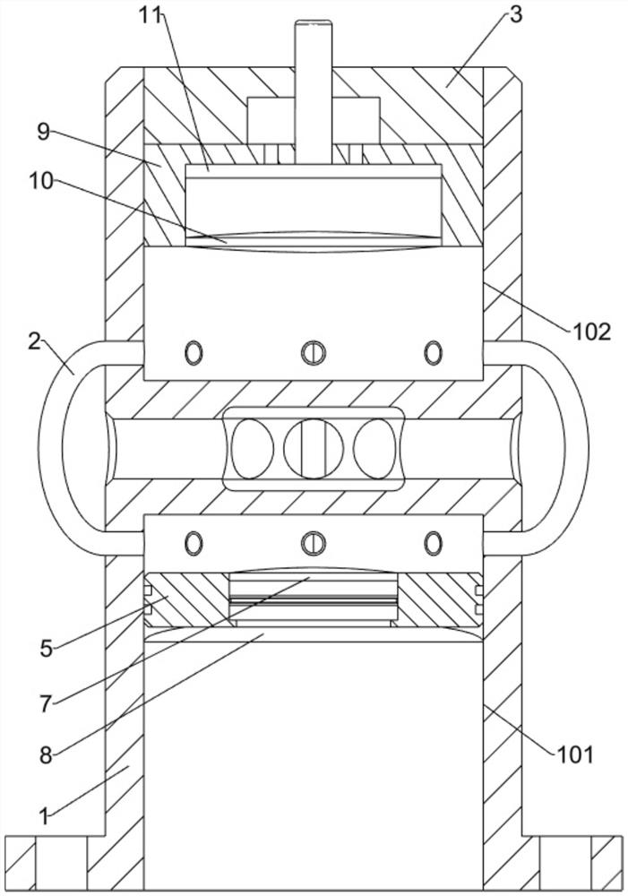
[0029] A power plant condenser vacuum identification calculation and detection device, such as Figure 1-Figure 3As shown, it includes a pressure transmission housing 1, the pressure transmission housing 1 is fixedly installed on the condenser housing through a flange, the lower part of the pressure transmission housing 1 is provided with a first pressure-reducing cavity 101, and the upper part of the pressure transmission housing 1 A second decompression cavity 102 is opened, and a cooling cavity 103 is opened in the middle of the pressure transmission shell 1. The cooling cavity 103 communicates with the outside world through a number of communication holes, and the cooling cavity 103 cooperates with its communication holes for cooling the pressure transmission shell. The body 1 is cooled during operation, and a number of pressure pipes 2 are fixed circumferentially in the middle of the pressure transmission shell 1. The plurality of pressure pipes 2 are used to communicate t...
Embodiment 2
[0032] On the basis of Example 1, as image 3 and Figure 4 As shown, the pressure buffer transmission assembly includes a buffer piston 5, the buffer piston 5 is sealed and slidably arranged in the first pressure-reducing cavity 101, a limit cavity is set in the middle of the buffer piston 5, and the limit cavity of the buffer piston 5 is slidably provided with a sensor The pressure piston 6, the upper part of the limiting cavity of the buffer piston 5 is fixedly installed with a first pressure diaphragm 7, the cavity between the pressure sensitive piston 6 and the first pressure diaphragm 7 is set as a liquid environment, the pressure sensitive piston 6 and the first pressure The diaphragms 7 are filled with non-deformable liquid. The small amount of liquid deformation makes the pressure-sensing piston 6 have a larger displacement matching relationship when the first pressure diaphragm 7 has the same amount of change. The middle of the first pressure diaphragm 7 is arranged ...
Embodiment 3
[0038] On the basis of Example 2, as figure 1 As shown, it also includes a cooling shell 13, the cooling shell 13 is fixedly installed on the outside of the middle of the pressure transmission shell 1, the pressure pipe 2 is located in the cooling shell 13, and the middle and upper parts of the cooling shell 13 are circumferentially provided with several Since the hot air moves upward, the heat is dissipated to the outside through the middle and upper through holes of the cooling casing 13 , and a fan 14 is arranged on the right part of the cooling casing 13 .
[0039] Since the pressure transfer shell 1 is installed on the condenser, the internal working environment temperature of the condenser is relatively high, which will affect the measurement environment of the pressure measuring gauge 4. Therefore, the pressure transfer shell 1 is cooled by the cooling shell 13, The operator starts the fan 14 to work, the fan 14 blows the gas into the cooling shell 13, the flowing gas t...
PUM
 Abstract
Description
Claims
Application Information
 - R&D
- Intellectual Property
- Life Sciences
- Materials
- Tech Scout
- Unparalleled Data Quality
- Higher Quality Content
- 60% Fewer Hallucinations
Browse by: Latest US Patents, China's latest patents, Technical Efficacy Thesaurus, Application Domain, Technology Topic, Popular Technical Reports.
© 2025 PatSnap. All rights reserved.Legal|Privacy policy|Modern Slavery Act Transparency Statement|Sitemap|About US| Contact US: help@patsnap.com