Magnetic levitation planar motor workbench with double-layer winding coarse and fine driving
A planar motor and double-layer winding technology, which is applied to the shape/style/structure of winding conductors, electromechanical devices, electrical components, etc., can solve the problems of difficult processing of special-shaped permanent magnets, large tracking errors, and large output fluctuations. Reliable technical support, small tracking error, and the effect of reducing output fluctuations
- Summary
- Abstract
- Description
- Claims
- Application Information
AI Technical Summary
Problems solved by technology
Method used
Image
Examples
Embodiment 1
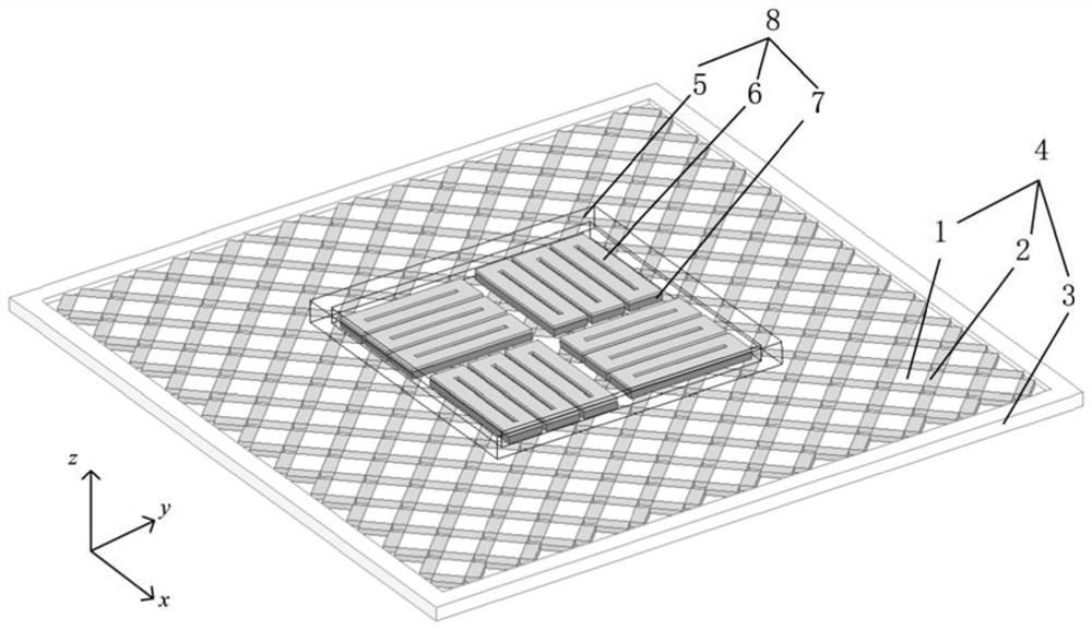
[0049] like figure 1 As shown, this embodiment provides a six-degree-of-freedom magnetic levitation plane motor table with double-layer winding rough and fine drive, including a stator 4 and a mover 8 .
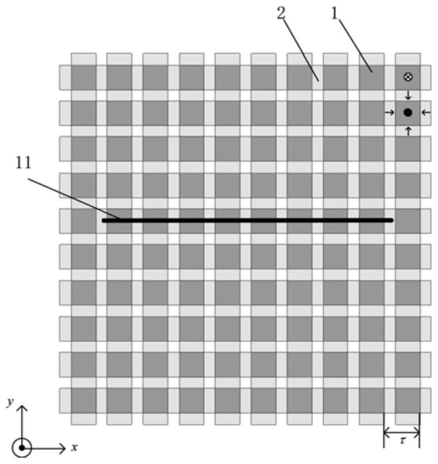
[0050] The stator 4 includes a plurality of vertically magnetized permanent magnets 1, a plurality of horizontally magnetized permanent magnets 2 and a base 3, wherein the plurality of vertically magnetized permanent magnets 1 and a plurality of horizontally magnetized permanent magnets 2 are arranged in a Halbach manner to form a permanent magnet. The magnetic array structure increases the magnetic field above the permanent magnet and weakens the magnetic field below, so the mover 8 is arranged above the permanent magnet array. The magnetization directions of the vertical magnetization permanent magnet 1 and the horizontal magnetization permanent magnet 2 are as follows: figure 2 shown by the arrow in the middle. The vertically magnetized permanent magnet 1 and the horizo...
Embodiment 2
[0062] The difference between this embodiment and the first embodiment is that the arrangement of the rectangular coils in the first winding 6 and the second winding 7 of the mover is different, and the relative positions of the first winding 6 and the second winding 7 are different. Other structures and connections All are the same as Example 1. details as follows:
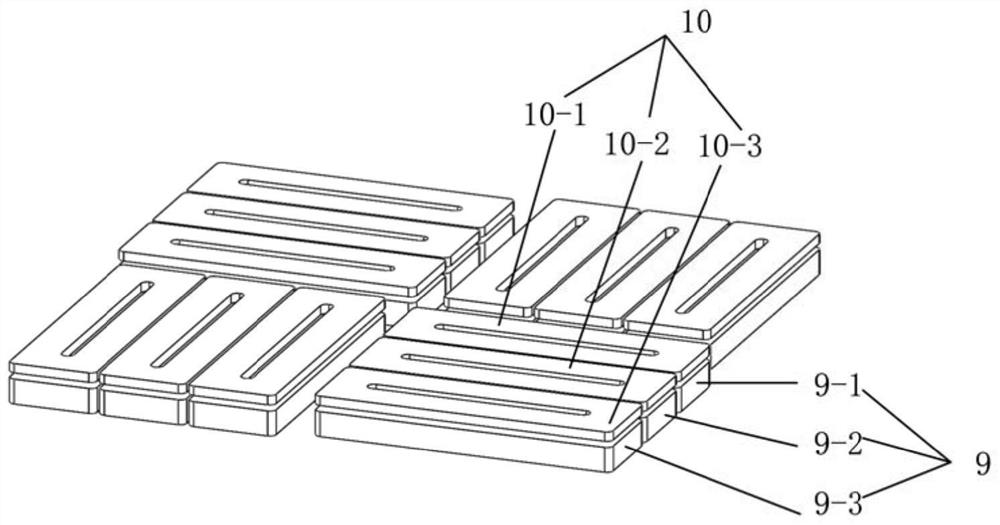
[0063] like Figure 4 As shown, in this embodiment, the first winding 6 includes three sets of second single-phase windings, and each second single-phase winding includes four rectangular coils stacked in sequence in a stepped shape, wherein one set of second single-phase windings is laid flat In the middle, the other two sets of second single-phase windings are vertically placed on the upper left and lower right steps of the second single-phase windings in the middle, and are attached to each other at the step connection of the second single-phase windings in the middle. The long sides of the rectangular coils...
Embodiment 3
[0066] The difference between this embodiment and the first embodiment is that the arrangement of the rectangular coils in the first winding 6 and the second winding 7 of the mover is different, and the relative positions of the first winding 6 and the second winding 7 are different. Other structures and connections All are the same as Example 1. details as follows:
[0067] like Figure 5 As shown, in this embodiment, the first winding 6 includes 7 rows, 2 rectangular coils in each row, the short sides of adjacent rectangular coils in each row are connected, and one rectangular coil in a row can be translated along the long side direction with another rectangular coil The coils are concentric, and the adjacent rows are staggered left and right.
[0068] The second winding 7 has the same structure and different thickness as the first winding 6. The long side of the rectangular coil in the first winding 6 and the long side of the rectangular coil in the second winding 7 are p...
PUM
 Abstract
Description
Claims
Application Information
 - R&D
- Intellectual Property
- Life Sciences
- Materials
- Tech Scout
- Unparalleled Data Quality
- Higher Quality Content
- 60% Fewer Hallucinations
Browse by: Latest US Patents, China's latest patents, Technical Efficacy Thesaurus, Application Domain, Technology Topic, Popular Technical Reports.
© 2025 PatSnap. All rights reserved.Legal|Privacy policy|Modern Slavery Act Transparency Statement|Sitemap|About US| Contact US: help@patsnap.com


