
Cooling circulation system

A circulation system and thermal cycle technology, applied in the direction of cooling/ventilation/heating transformation, etc., can solve the problems of reduced heat transfer efficiency, reduced heat transfer efficiency of heat transfer media, and closed pipeline air cannot be effectively discharged, so as to ensure Heat transfer efficiency, effect of good heat transfer efficiency

Pending Publication Date: 2022-07-29
无锡泓帆智能科技有限公司
View PDF1 Cites 0 Cited by
  • Summary
  • Abstract
  • Description
  • Claims
  • Application Information

AI Technical Summary

Problems solved by technology

Such as the aforementioned prior art for server cooling, after installation and start-up, it is necessary to inject a heat exchange medium (for example, water or antifreeze coolant) into the closed pipeline, and the air in the closed pipeline cannot be effectively discharged. ;In addition, because the heat exchange medium dissolves a certain amount of air, when the cooling system is started, the heat exchange medium circulates to the server to cool the server through the heat exchange effect of the heat exchange medium. The heat exchange medium absorbs heat and causes gas to be released, thereby generating air bubbles in the closed pipe, resulting in a greatly reduced heat exchange efficiency
Therefore, no matter in the start-up process of the cooling system or in the operation process, there is a defect that the heat exchange efficiency of the heat exchange medium is greatly reduced due to the existence of a certain amount of air in the closed pipe, which leads to the use in the prior art The heat exchange efficiency of the cooling circulation system that cools down the heat-generating devices such as servers (or data centers) is not good

Method used


Image

  • Cooling circulation system
  • Cooling circulation system
  • Cooling circulation system

Examples


Embodiment Construction

[0037] The present invention will be described in detail below with reference to the various embodiments shown in the accompanying drawings, but it should be noted that these embodiments do not limit the present invention. Equivalent transformations or substitutions all fall within the protection scope of the present invention.

[0038] It should be understood that in this application, the terms "center", "longitudinal", "lateral", "length", "width", "thickness", "upper", "lower", "front", "rear" , "left", "right", "vertical", "horizontal", "top", "bottom", "inside", "outside", "axial", "radial", etc. indicate the orientation or position relationship as Based on the orientation or positional relationship shown in the accompanying drawings, it is only for the convenience of describing the technical solution and simplifying the description, rather than indicating or implying that the referred device or element must have a specific orientation, be constructed and operated in a sp...


PUM


Abstract

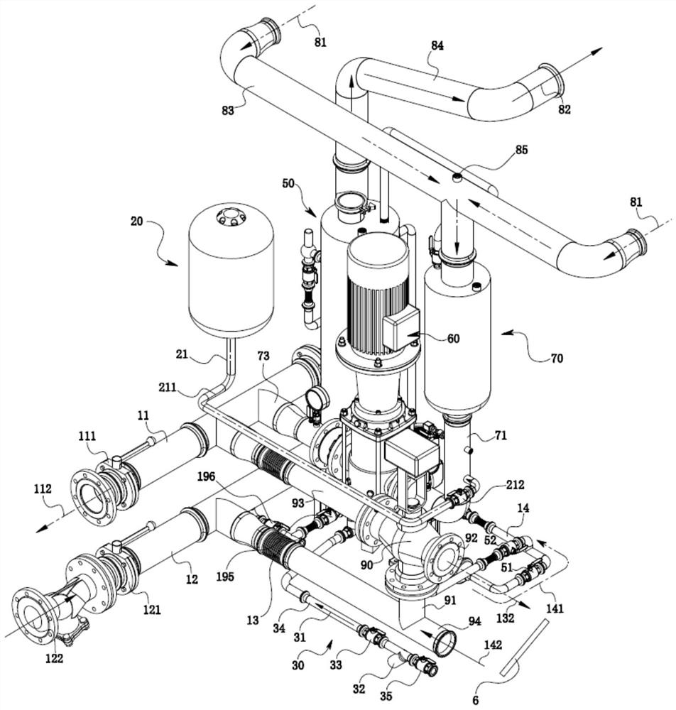
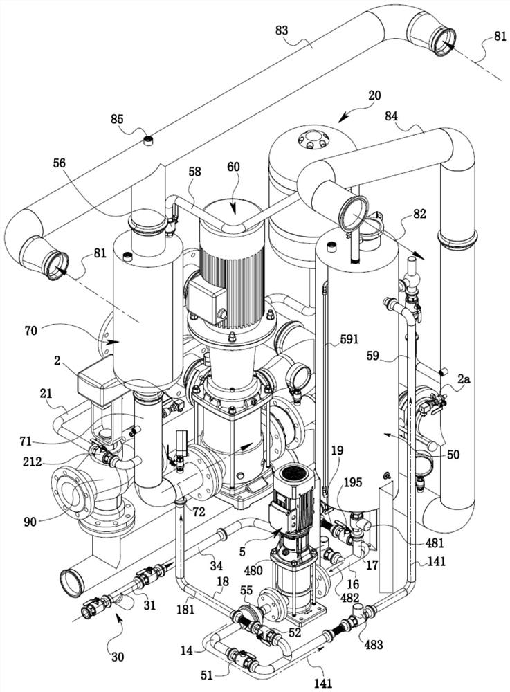
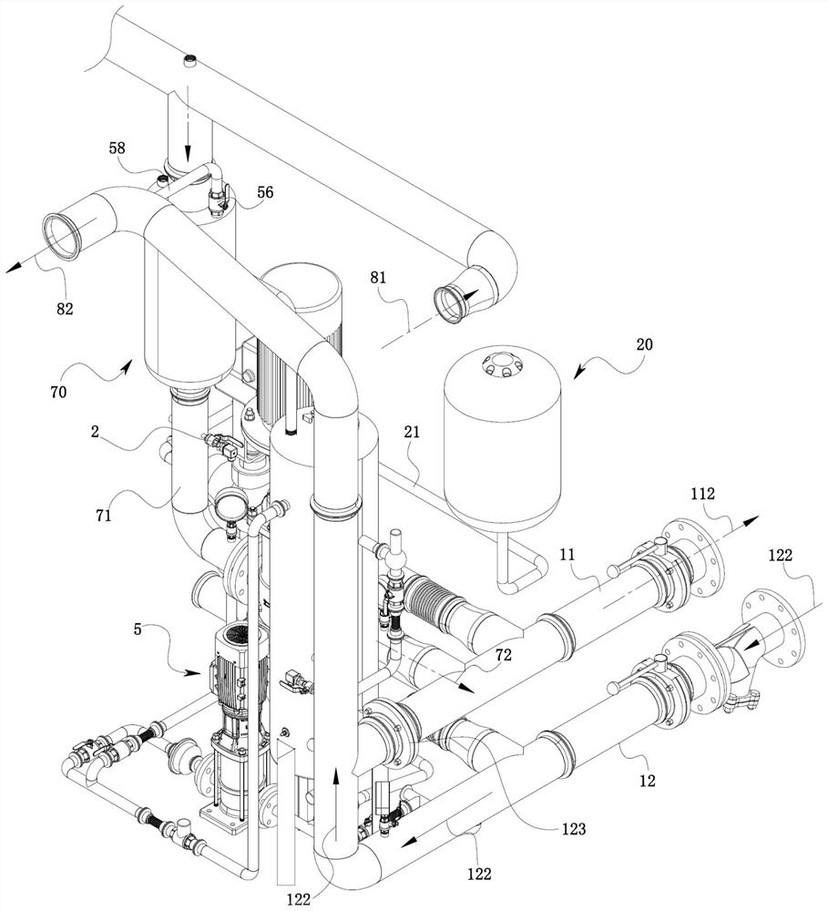
The invention provides a cooling circulation system which is connected to a load generating heat and comprises a circulation pump, a heat exchange circulation pipeline, a heat absorption circulation pipeline, a degassing device connected to the circulation pump and the heat absorption circulation pipeline and a surge tank. After the heat exchange medium flows through the degassing device, the heat exchange medium is pumped into the heat exchange circulating pipeline under the driving of the circulating pump, and the heat exchange circulating pipeline enables the cooled heat exchange medium to flow back into the heat absorption circulating pipeline again; the pressure stabilizing tank is connected into a second pipeline arranged between the degassing device and the circulating pump through a first pipeline, the second pipeline is provided with a pressure sensor, and when the pressure in the second pipeline is lower than a preset pressure threshold value, the pressure stabilizing tank presses a heat exchange medium into the second pipeline through the first pipeline; the pressure in the second pipeline is kept to be greater than or equal to a preset pressure threshold value. Through the application, the pressure of the heat exchange medium output to the load by the cooling circulation system is constant, and air can be effectively exhausted, so that the heat exchange efficiency is ensured.

Description

technical field [0001] The invention relates to the technical field of heat exchange equipment, and more particularly to a cooling cycle system. Background technique [0002] A data center deployment consists of a large number of servers, and a server cluster is formed by the deployment of multiple servers. The server generates a lot of heat during operation, so it needs a cooling system to dissipate it. Compared with air cooling, the water cooling system has a better heat dissipation effect due to its larger specific heat capacity. [0003] After searching, the applicant found that the Chinese utility model patent with the publication number CN214792726U discloses a data center using tap water for cooling and waste heat recovery. The prior art realizes cooling and waste heat recovery through booster pumps, return pumps and pipes. During the process of injecting a heat exchange medium (for example, water or antifreeze coolant) into the closed pipe after installation and s...

Claims


Application Information

Patent Timeline
IPC IPC(8): H05K7/20
CPCH05K7/20763
Inventor 魏立国
Owner 无锡泓帆智能科技有限公司
Learn More