
Accelerator ground wire system based on EMC and design method

A ground wire system and design method technology, applied in the direction of connecting contact materials, electrical components, magnetic field/electric field shielding, etc., can solve problems such as complex equipment composition, ground circulation interference, equipment malfunction, etc., to improve safety protection performance, Good suppression effect, the effect of reducing ground wire impedance

Pending Publication Date: 2022-07-29
INST OF MODERN PHYSICS CHINESE ACADEMY OF SCI
View PDF0 Cites 0 Cited by
  • Summary
  • Abstract
  • Description
  • Claims
  • Application Information

AI Technical Summary

Problems solved by technology

However, from the analysis of electromagnetic compatibility performance, this kind of ground wire structure will cause serious common ground impedance interference problems between equipment due to the long PE wire and high ground wire impedance.
For this reason, the accelerator device is usually laid with a dedicated ground grid. According to the TN-S repeated grounding method, the equipment side is grounded nearby, which alleviates the problem of high impedance of the ground wire, but will cause ground circulation interference; if only a dedicated ground grid is used, That is, the TT power distribution system, although it realizes the nearby grounding of equipment and alleviates the problem of ground circulation, it does not meet the requirements of power distribution safety regulations
In addition, the accelerator device system is huge and the equipment composition is complex. Due to the failure to adopt a reasonable ground wire scheme, it has become an important interference path-transient high voltage and high-frequency noise such as surges and bursts pass through the ground wire and cause equipment malfunctions , or even damage; at the same time, the conduction emission noise crosstalks through the ground wire, which affects the detection of weak signals and increases the difficulty of scientific research experiments

Method used


Image

  • Accelerator ground wire system based on EMC and design method
  • Accelerator ground wire system based on EMC and design method
  • Accelerator ground wire system based on EMC and design method

Examples


Embodiment Construction

[0038] In order to make the purpose, technical solutions and advantages of the embodiments of the present invention clearer, the technical solutions of the embodiments of the present invention will be clearly and completely described below with reference to the accompanying drawings of the embodiments of the present invention. Obviously, the described embodiments are some, but not all, embodiments of the present invention. Based on the described embodiments of the present invention, all other embodiments obtained by those of ordinary skill in the art fall within the protection scope of the present invention.

[0039] It should be noted that the terminology used herein is for the purpose of describing specific embodiments only, and is not intended to limit the exemplary embodiments according to the present application. As used herein, unless the context clearly dictates otherwise, the singular is intended to include the plural as well, furthermore, it is to be understood that w...


PUM


Abstract

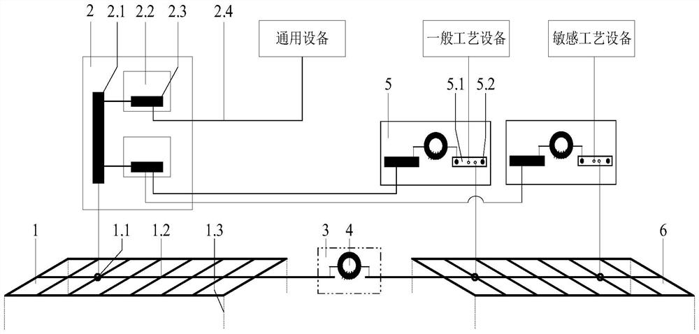
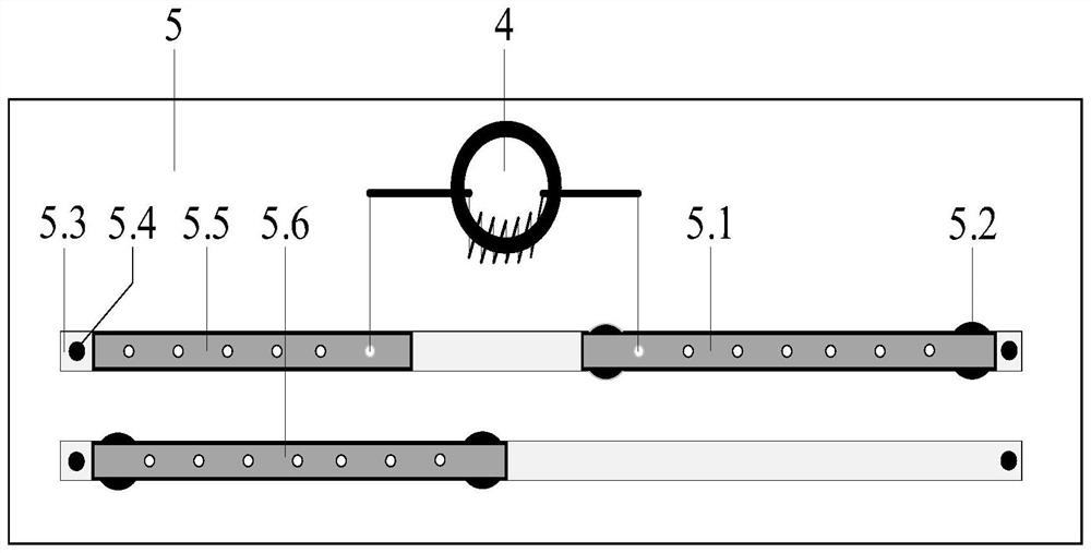
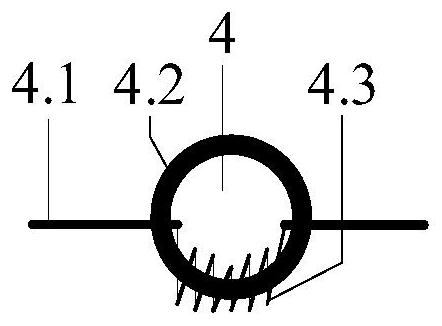
The invention relates to an accelerator ground wire system based on EMC (Electro Magnetic Compatibility) and a design method, and the system comprises a universal ground net which is arranged at a universal equipment side and is a main grounding net of universal equipment, and the universal equipment is connected with the universal ground net through a low-voltage power distribution system of a power distribution room to realize safe grounding; the process ground net is laid nearby process power distribution equipment and is a main grounding net of the process power distribution equipment, the process equipment is connected with the process ground net through a grounding box, and differential grounding of the process ground net is achieved through the grounding box; and the grounding well is used for connecting the general ground screen and the process ground screen, realizing high-frequency isolation and power frequency combination between the general ground screen and the process ground screen, and serving as a grounding test point. The device can give consideration to safety protection and electromagnetic compatibility, and can be applied to the field of accelerator electromagnetic compatibility and grounding.

Description

technical field [0001] The invention relates to the technical field of accelerator electromagnetic compatibility and grounding, in particular to an EMC-based accelerator grounding system and a design method. Background technique [0002] With the development of technology, the electromagnetic interference problem of large scientific devices such as accelerators has become increasingly prominent - the system failure rate and electromagnetic noise level are high, which affects the quality of beam current and scientific research experiments. The ground wire is one of the important ways of electromagnetic interference, which is related to the safety protection and electromagnetic compatibility performance of the accelerator device. The accelerator device generally adopts the TN-S power distribution system - the equipment is connected to the PE line, and the overcurrent device operates and protects when a ground fault occurs. However, from the analysis of electromagnetic compati...

Claims


Application Information

Patent Timeline
Patent Type & Authority Applications(China)
IPC IPC(8): H05K9/00H01R4/64H01R4/66
CPCH05K9/0064H01R4/66H01R4/64
Inventor 封安辉刘鹏飞刘晔周忠祖杨建成张永搏孙鹏张润祖赵江程永琪
Owner INST OF MODERN PHYSICS CHINESE ACADEMY OF SCI
Learn More