Motorcycle engine right box end face milling tool

An engine and end face milling technology, applied in the field of fixtures, can solve the problems of time consumption, unfavorable flexibility, unfavorable long-term use of devices, etc., to achieve the effect of ensuring stability and improving flexibility

Pending Publication Date: 2022-08-02
刘振朝
0 Cites 0 Cited by

AI-Extracted Technical Summary

Problems solved by technology

[0003] 1. The existing tooling for milling the end face of the right case of a motorcycle engine generally uses a clamping plate of a fixed size to clamp the workpiece. When the size of the workpiece to be processed is different, a different clamping plate needs to be replaced. This process is very time-consuming. detrimental to the flexibility of use ...

Method used

Further, drive translation screw rod 22 to rotate by drive motor 21, drive bottom installation head 61 to move to the right by translation screw rod 22, simultaneously, thus bottom installation head 61 adopts cross bar 62 to connect, thus guarantees bottom installation head 61 activity stability, the installation head 61 on the top of the clamping device 6 moves to the right along the limit rod 4, so that the entire clamping device 6 can move stably, and then the workpiece can be clamped and fastened, and, through the movement The sleeve 64 and the movable rod 65 can adjust the height of the clamping device 6, so that workpieces of different heights can be clamped, thereby improving the flexibility of the device.
Further, the driving gear 33 is driven by the lifting motor 32 to rotate, and the driving gear 33 drives the follower gear 34 to rotate, so that the transmission belt 36 can move, and the lifting slider 38 is carried out by the positioning block 37 on the transmission belt 36 Positioning, control the lifting slider 38 to carry out lifting activities, and improve the stability of the mounting shell 71 lifting through the guide vertical bar 391 at the bottom of the connecting plate 39, here, the mounting shell 71 uses the rotary head 77 to control the tightness of the fixed screw rod 76, In this way, the height of the mounting shell 71 is adjusted, thereby facilitating the matching of the carrying plate with workpieces of different heights.
It is worth mentioning that the rotation of the rotating shaft 81 is driven by the rotating motor 88, thereby adjusting the orientation of the frock, here, the rotation of the placement platfo...

Abstract

The invention discloses a motorcycle engine right box end face milling tool, and relates to the technical field of tool clamps, the motorcycle engine right box end face milling tool comprises a placing platform, and a driving device is arranged on the inner side of the placing platform. The height of the clamping device can be adjusted through a movable sleeve and a movable rod, so that workpieces with different heights can be clamped, the use flexibility of the device is improved, a guide rod is mounted on the inner wall of a mounting shell, a movable plate is elastically supported through an elastic piece, and then after the workpieces are fixed by the clamping device, the clamping device is fixed to the guide rod. When the tool is used for machining the workpiece, the bearing plate on the left side of the butt-joint plate connecting block is attached to the right side of the workpiece, the tool can directly penetrate through the workpiece through the hole formed in the surface of the bearing plate, and the tool device is prevented from being damaged by the tool through elastic supporting of the elastic piece, so that the service life of the tool device is prolonged advantageously.

Application Domain

WorkpiecesMilling machines +5

Technology Topic

Automotive engineeringManufacturing engineering +1

Image

  • Motorcycle engine right box end face milling tool
  • Motorcycle engine right box end face milling tool
  • Motorcycle engine right box end face milling tool

Examples

  • Experimental program(3)

Example Embodiment

[0034] Example 1
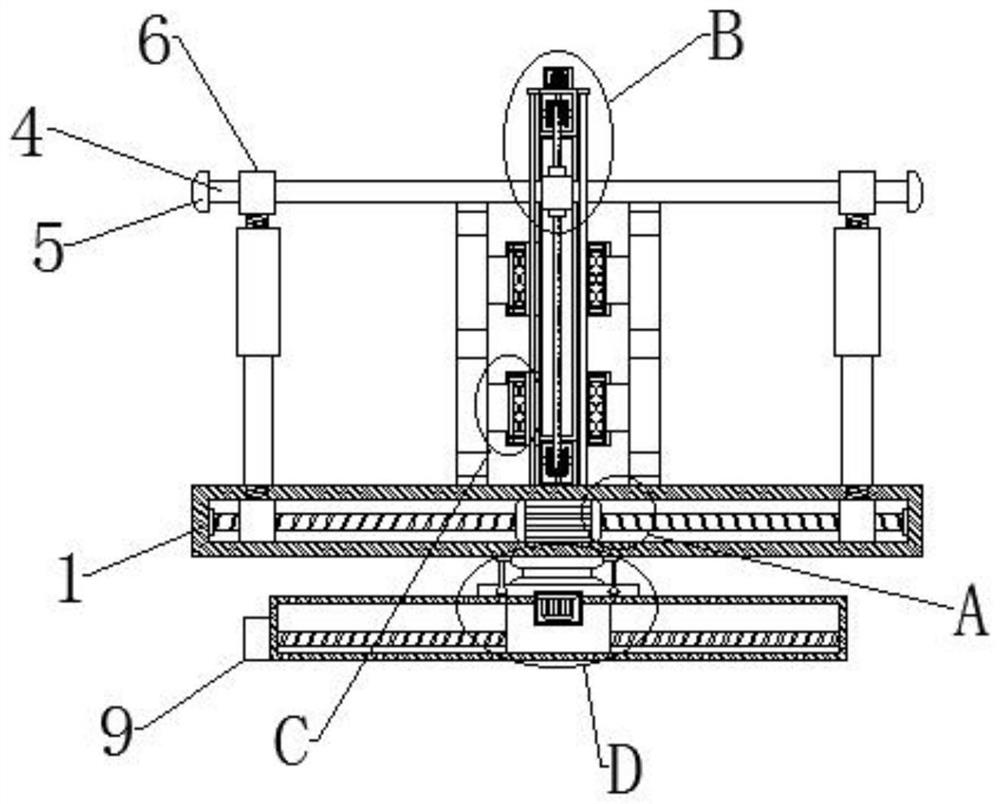
[0035] like Figure 1-8 As shown, it includes a placing platform 1, the inner side of the placing platform 1 is provided with a driving device 2, the top center of the placing platform 1 is provided with a lifting device 3, a limit rod 4 is provided above the left side of the lifting device 3, and the left end of the limit rod 4 is provided The limit block 5 is fixedly connected, the outer wall of the limit rod 4 is provided with a clamping device 6, the middle of the left side of the lifting device 3 is provided with a buffer device 7, the bottom of the placing platform 1 is provided with a rotating device 8, and the left side of the rotating device 8 is provided A transmission device 9 is provided, the clamping device 6 includes a movable sleeve 64, the inner wall of the movable sleeve 64 is movably connected with a movable rod 65, the buffer device 7 includes a mounting shell 71, and the inner wall of the mounting shell 71 is movably connected with a movable plate 72, which is movable. One side of the outer wall of the plate 72 is fixedly connected with a butt plate connecting block 73 .
[0036] Preferably, a threaded head 63 is fixedly connected to the top of the movable sleeve 64, an installation head 61 is movably connected to the outer wall of the threaded head 63, a transverse rod 62 is fixedly connected to one side of the outer wall of the installation head 61, and the inner wall of the installation head 61 is connected to the limit rod The outer wall of 4 is movably connected, the top of the movable rod 65 is fixedly connected with a spring 66 , and the top of the spring 66 is fixedly connected with the top of the inner wall of the movable sleeve 64 .
[0037] Further, the translation screw 22 is driven to rotate by the driving motor 21, and the bottom mounting head 61 is driven to move to the right by the translation screw 22. At the same time, the bottom mounting head 61 is connected by the cross bar 62, thereby ensuring the movable bottom mounting head 61. For stability, the mounting head 61 on the top of the clamping device 6 moves to the right along the limit rod 4, so that the entire clamping device 6 can move stably, and then the workpiece can be clamped and tightened. The movable rod 65 can adjust the height of the clamping device 6 so as to clamp workpieces with different heights, thereby improving the flexibility of the device.
[0038] Preferably, the inner wall of the movable plate 72 is movably connected with a guide rod 74 , the left and right ends of the guide rod 74 are fixedly connected with the inner wall of the mounting shell 71 , the other side of the outer wall of the movable plate 72 is fixedly connected with a spring piece 75 , and the right side of the spring piece 75 is fixedly connected. It is fixedly connected to the right side of the inner wall of the installation shell 71 , a fixed screw 76 is movably connected inside the installation shell 71 , and a rotating head 77 is fixedly connected to one end of the fixed screw 76 .
[0039] Further, the guide rod 74 is installed on the inner wall of the installation shell 71, and the movable plate 72 is elastically supported by the elastic piece 75, and then after the clamping device 6 is fixed to the workpiece, when the workpiece is processed by the tool, the connecting block 73 is connected by the docking plate. The carrier plate on the left is attached to the right side of the workpiece, and the tool can directly penetrate the workpiece through the holes on the surface of the carrier plate, and the elastic support of the elastic sheet 75 is used to avoid damage to the tooling device itself by the tool, which is beneficial to Increase the service life of the device.

Example Embodiment

[0040] Example 2
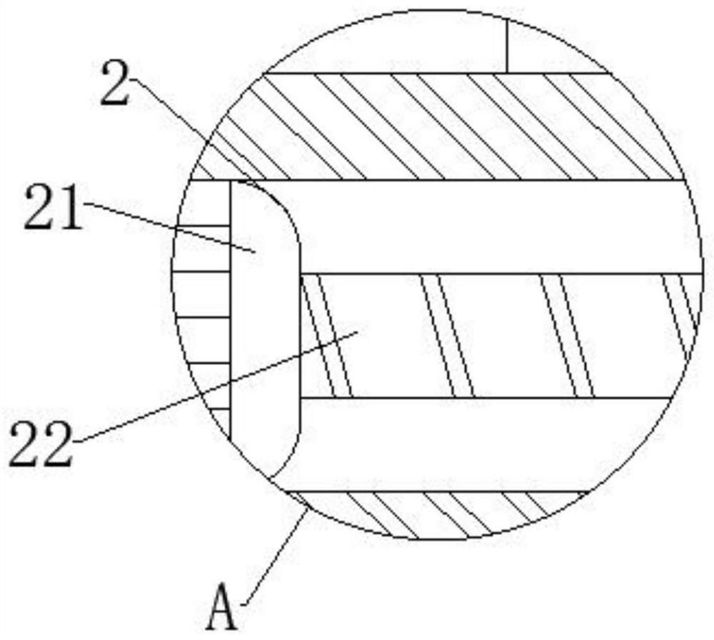
[0041] like Figure 1-8 As shown, the driving device 2 includes a driving motor 21, the output shaft of the driving motor 21 is fixedly connected with a translation screw 22, the outer wall of the translation screw 22 is movably connected with the inner wall of the mounting head 61, and the outer wall of the driving motor 21 is connected with the inner wall of the placing platform 1. Fixed connection.
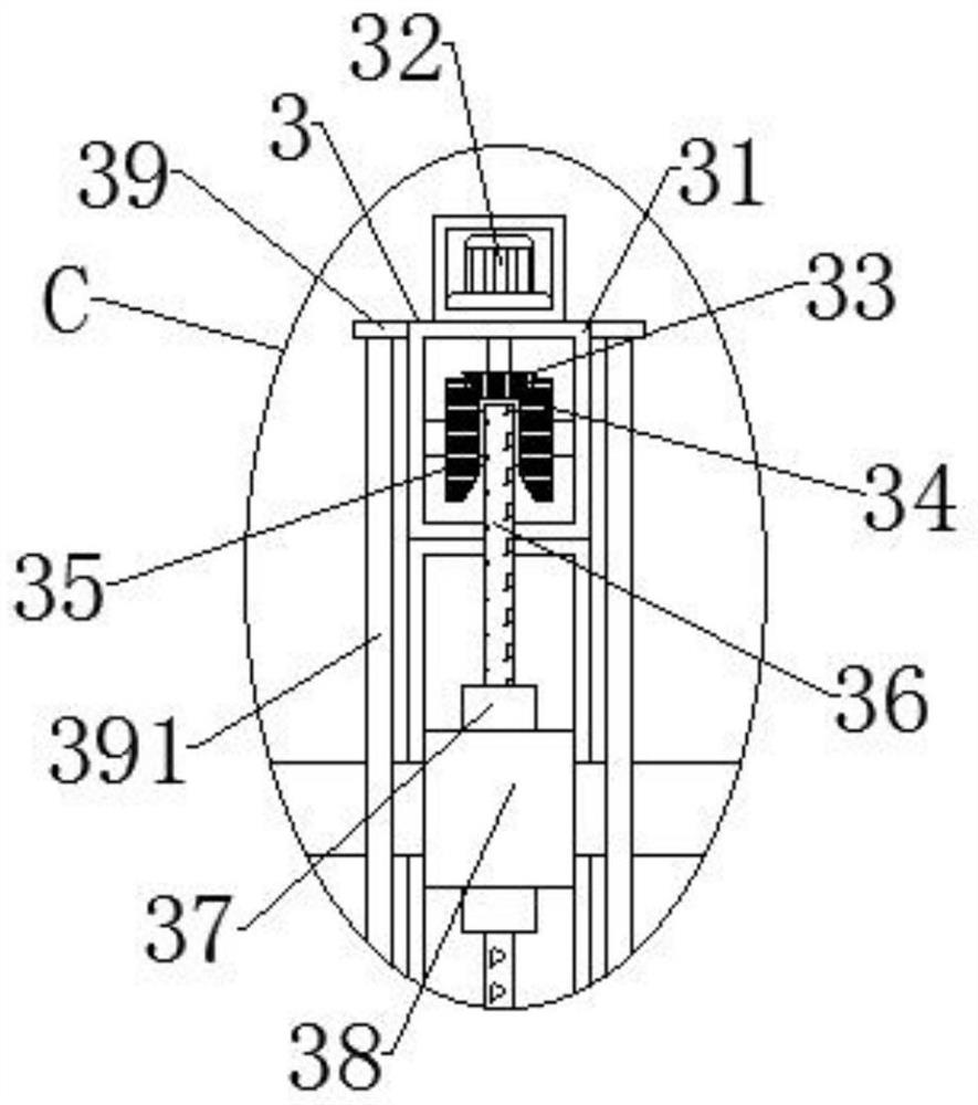
[0042] Preferably, the lifting device 3 includes a lifting groove 31, a lifting motor 32 is fixedly connected to the top of the lifting groove 31, a driving gear 33 is fixedly connected to the output shaft of the lifting motor 32, and a follower gear 34 is movably connected to the outer wall of the driving gear 33, The inside of the follower gear 34 is provided with a connecting shaft 35, the outer wall of the connecting shaft 35 is movably connected with a transmission belt 36, the outer wall of the transmission belt 36 is fixedly connected with a positioning block 37, and the bottom of the positioning block 37 is movably connected with a lifting slider 38, a lifting groove. A connecting plate 39 is fixedly connected to one side of the outer wall of 31 , and a guide vertical rod 391 is fixedly connected to the bottom of the connecting plate 39 .
[0043] Further, the driving gear 33 is driven to rotate by the lifting motor 32, and then the driven gear 34 is driven to rotate by the driving gear 33, so that the transmission belt 36 can move, and the lifting slider 38 is positioned by the positioning block 37 on the transmission belt 36. The lifting slider 38 is controlled to lift and lower, and the vertical guide rod 391 at the bottom of the connecting plate 39 improves the stability of the lifting and lowering of the mounting shell 71. The height of the mounting shell 71 is adjusted, thereby facilitating the matching of the carrier plate with workpieces of different heights.

Example Embodiment

[0044] Example 3
[0045] like Figure 1-8 As shown, the rotating device 8 includes a rotating shaft 81, the top of the rotating shaft 81 is fixedly connected with the bottom surface of the placing platform 1, the bottom of the rotating shaft 81 is fixedly connected with a horizontal plate 82, and one side of the outer wall of the rotating shaft 81 is fixedly connected with a connecting seat 83, the connecting seat The bottom of 83 is fixedly connected to the limit vertical rod 84 , and the bottom of the outer wall of the limit vertical rod 84 is movably connected to the inner wall of the horizontal plate 82 .
[0046] Preferably, an installation groove 85 is fixedly connected to the bottom of the horizontal plate 82 , and a translation slider 86 is movably connected to the inner wall of the installation groove 85 . A rotating motor 88 is fixedly connected to the inner wall of 87 , and the output shaft of the rotating motor 88 is fixedly connected to the bottom of the rotating shaft 81 .
[0047] Preferably, the transmission device 9 includes a casing 91 , the outer wall of the casing 91 is fixedly connected to the left side of the mounting groove 85 , the inner wall of the casing 91 is fixedly connected with a mounting plate 92 , and one side of the outer wall of the mounting plate 92 is fixedly connected with a sliding The motor 93, the output shaft of the sliding motor 93 is fixedly connected with a transmission wheel 94, and the outer wall of the transmission wheel 94 is movably connected with an energy transmission belt 95.
[0048] It is worth mentioning that the rotating shaft 81 is driven by the rotating motor 88 to adjust the orientation of the tooling. Here, the limit vertical rod 84 is movably connected with the horizontal plate 82 to stabilize the rotation of the placing platform 1 and prevent it from rotating. During the process of tilting, the transmission wheel 94 is driven by the sliding motor 93, and then the energy transmission belt 95 is driven to rotate through the transmission wheel 94, thereby simultaneously driving the front and rear sliding screws to rotate, thus, the sliding screws drive the translation slider 86. The left and right movements are carried out, and then the position of the tooling is changed, which facilitates the cooperation of the tools, so as to process better products, thereby improving the quality superiority of the device for processing the workpiece.
[0049] The working principle of the milling end face tooling for the right box of the motorcycle engine is described in detail below.
[0050] like Figure 1-8 As shown, the motorcycle engine right box milling end face tooling, when in use, first drives the drive gear 33 to rotate through the lift motor 32, and then drives the follower gear 34 to rotate through the drive gear 33, so that the transmission belt 36 can move, and pass the transmission belt 36. The positioning block 37 locates the lifting slider 38, and controls the lifting slider 38 to move up and down. By adjusting the position of the lifting slider 38, the limit rod 4 is moved up and down, thereby controlling the height of the mounting head 61, thereby controlling the clamping Height of device 6.
[0051] Then, the vertical guide rod 391 at the bottom of the connecting plate 39 improves the stability of the lifting and lowering of the mounting shell 71. Here, the mounting shell 71 uses the rotating head 77 to control the tightness of the fixing screw 76, thereby adjusting the height of the mounting shell 71, thereby facilitating the The carrier plate is matched with workpieces of different heights, and one side of the workpiece is attached to the carrier plate, the translation screw 22 is driven to rotate by the driving motor 21, and the bottom mounting head 61 is driven to the right by the translation screw 22. At the same time, the bottom mounting head 61 is connected by a cross bar 62, thereby ensuring the stability of the movement of the bottom mounting head 61, and the mounting head 61 on the top of the clamping device 6 moves to the right along the limit rod 4, so that the entire clamping device 6 can move stably, The workpiece can then be clamped and tightened.
[0052] Next, the guide rod 74 is installed on the inner wall of the installation shell 71, and the movable plate 72 is elastically supported by the elastic piece 75, and then the workpiece is fixed by the clamping device 6. When the workpiece is processed by a tool, the left side of the connection block 73 is connected by the docking plate 6. The carrier plate is attached to the right side of the workpiece, the tool can directly penetrate the workpiece through the holes on the surface of the carrier plate, and the elastic support of the elastic sheet 75 is used to avoid damage to the tooling device itself by the tool. 88 drives the rotating shaft 81 to rotate, thereby adjusting the orientation of the tooling. Here, the rotation of the placing platform 1 is stabilized by the movable connection between the limit vertical rod 84 and the horizontal plate 82, so as to avoid tilting during the rotation process, and then slide The motor 93 drives the transmission wheel 94 to drive, and then drives the energy transmission belt 95 to rotate through the transmission wheel 94, thereby simultaneously driving the front and rear sliding screws to rotate, thus, the sliding screws drive the translation slider 86 to move left and right, and then make the tooling The position changes, which facilitates the tool to cooperate, resulting in a better quality product.

PUM

no PUM

Description & Claims & Application Information

We can also present the details of the Description, Claims and Application information to help users get a comprehensive understanding of the technical details of the patent, such as background art, summary of invention, brief description of drawings, description of embodiments, and other original content. On the other hand, users can also determine the specific scope of protection of the technology through the list of claims; as well as understand the changes in the life cycle of the technology with the presentation of the patent timeline. Login to view more.

Similar technology patents

Four-rotor aircraft safety control method based on high-order disturbance observer

ActiveCN110320925AEliminate modeling errorsGuaranteed stability
Owner:NANJING UNIV OF AERONAUTICS & ASTRONAUTICS

Complete locating device for total hip arthroplsty

PendingCN107149490AReduce the chance and degree of loosening or saggingGuaranteed stability
Owner:汤向阳

Classification and recommendation of technical efficacy words

  • increase flexibility
  • Guaranteed stability

Front illuminated back side contact thin wafer detectors

InactiveUS7057254B2reduce radiation damage susceptibilityincrease flexibility
Owner:OSI OPTOELECTRONICS

Security guarantee method and system for Windows terminals based on auto white list

InactiveCN101650768Aincrease flexibilityImprove the range of adaptation
Owner:SHENZHEN Y& D ELECTRONICS CO LTD

Data processing method and system

InactiveUS20070018986A1increase flexibility
Owner:IBM CORP

A ccd-type colloidal gold immunochromatographic diagnostic test paper quantitative analysis system

InactiveCN102279263AGuaranteed stabilityAddressing Subjective Bias
Owner:杭州顿力医疗器械有限公司

General clamp for abrasive flow polishing of complicated hole surface

InactiveCN104551985AContinuous and stable flowGuaranteed stability
Owner:CHANGCHUN UNIV OF SCI & TECH
Why Eureka
Try Eureka