Eddy current braking device and braking method thereof

An eddy current braking and braking component technology, applied in electric braking systems, asynchronous inductive clutches/brakes, electric vehicles, etc., can solve the problem of low energy utilization rate of electromagnets, affecting the lightweight design of trains, loss of braking force, etc. problems, to reduce excess loss, reduce weight, and extend the life of components

Active Publication Date: 2022-08-02
SOUTHWEST JIAOTONG UNIV
View PDF14 Cites 6 Cited by
  • Summary
  • Abstract
  • Description
  • Claims
  • Application Information

AI Technical Summary

Problems solved by technology

[0003] However, electromagnetic eddy current braking is to generate a magnetic field by passing excitation current into the electromagnet. When the circuit fails, the loss of excitation will directly lead to the loss of braking force. To avoid this, it is necessary to install electromagnetic eddy current brakes on the vehicle. A large-capacity backup battery dedicated to braking, and the energy required for excitation when electromagnetic eddy current braking is applied is high, while the energy utilization rate of the electromagnet is low, which not only makes the efficiency of electromagnetic eddy current braking low, but also affects the weight of the train design

Method used


Image

  • Eddy current braking device and braking method thereof
  • Eddy current braking device and braking method thereof
  • Eddy current braking device and braking method thereof

Examples


Embodiment 1

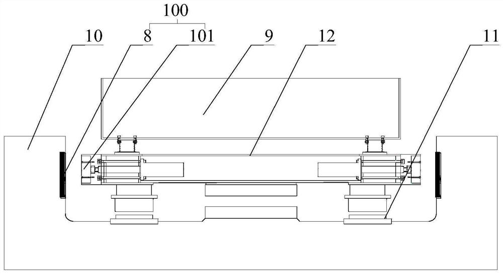
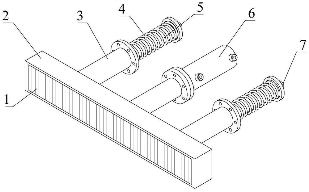
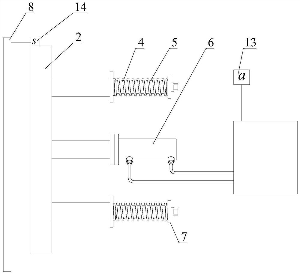
[0032] The present invention provides an eddy current braking device 100, comprising an induction plate 8 disposed on the inner wall of the track base 10 and braking assemblies 101 disposed on both sides of the suspension frame frame 12, the induction plate 8 along the track base 10 is arranged in the extension direction, and the induction plate 8 is made of conductive non-ferromagnetic material; wherein, the brake assembly 101 includes a lifting mechanism and a magnet base 2, and one end of the lifting mechanism is connected to the suspension frame 12. The outer surface perpendicular to the ground is connected; the magnet base 2 is connected to the other end of the lifting mechanism, the magnet base 2 and the induction plate 8 are located at the same height and parallel to each other, and the magnet base 2 is close to the induction A plurality of permanent magnets 1 are arranged on the surface of the plate 8 uniformly and without gaps along the extending direction of the track...

Embodiment 2

[0041] The present invention also provides a braking method of the eddy current braking device 100. The magnetic levitation train adopts the above-mentioned eddy current braking device 100 for braking, and the braking method includes:

[0042] When the magnetic levitation train is braked, the eddy current braking device 100 works so that the lifting mechanisms arranged on both sides of the suspension frame 12 reciprocate linearly along its axial direction; the magnet base 2 follows the movement of the lifting mechanism It is close to the induction plate 8 disposed on the inner wall of the track base 10 ; along with the movement of the suspension frame 12 , the magnet base 2 is moved relative to the induction plate 8 , and the induction plate 8 cuts the The magnetic field lines of the permanent magnet 1 on the magnet base 2 generate an eddy current; the eddy current generates a Loren magnetic force opposite to the driving direction of the vehicle body 9 under the action of the m...

Embodiment 3

[0044] This embodiment is based on the above-mentioned Embodiment 2, and the braking method of the eddy current braking device 100 further includes: the track base 10 is provided with different speed sections along the extending direction thereof, and different speed sections are set in different speed sections. The induction plate 8, the setting method of the induction plate 8 includes steps S1, S2, S3 and S4, wherein:

[0045] Step S1, obtain first information and second information, the first information is the preset driving speed corresponding to the current speed segment; the second information is the permanent magnet array in the magnet base 2 along the track The length information of the extension direction of the base 10, the permanent magnet array is arranged in a Halbach array. In this step, the preset driving speed in this section is determined according to various factors such as the development degree, line length, topography and geology and hydrological conditio...


PUM


Abstract

The invention provides an eddy current braking device and a braking method thereof, and relates to the technical field of magnetic suspension braking devices. According to the application, when the magnetically levitated train in high-speed running needs to be braked, the driving motor works, so that the lifting mechanism pushes the magnet seat outwards and gets close to the induction plate, and the suspension framework moves to drive the magnet seat to move in the extension direction of the magnetic track; the induction plate fixedly arranged on the track base generates eddy current due to the fact that the induction plate cuts magnetic induction lines of the permanent magnet on the magnet base, the eddy current generates Lorentz force under the action of the magnetic field of the permanent magnet to serve as braking force, and the magnitude of the braking force can be controlled by adjusting the spacing distance between the induction plate and the magnet base. The permanent magnets are adopted to replace electromagnets for excitation, no heat effect is generated, redundant loss of parts caused by unnecessary heat loads is reduced, and the service life of the parts is prolonged. And an additional power supply is not needed to provide an electromagnetic field, so that a large amount of power is saved, and the weight of suspension equipment on the bogie is greatly reduced.

Description

technical field [0001] The present invention relates to the technical field of magnetic suspension braking devices, in particular, to an eddy current braking device and a braking method thereof. Background technique [0002] With the development of society, people's demand for higher-speed rail transit systems is also increasing, and the increase in train running speed puts forward higher requirements for the performance of the braking system, which must enable high-speed running vehicles to obtain effective braking to achieve safe and smooth parking. The outstanding advantages of eddy current braking are that there is no mechanical wear, no odor, no noise, the braking force has a flat characteristic in a large speed range, and the braking force is controllable. Eddy current braking can make the vehicle maintain a high deceleration during the deceleration process, shorten the braking distance, reduce wear and improve the running economy. [0003] However, electromagnetic e...

Claims


Application Information

Patent Timeline
Patent Type & Authority Applications(China)
IPC IPC(8): B60L7/28H02K49/04
CPCB60L7/28H02K49/04B60L2200/26Y02T10/64
Inventor 张卫华邓自刚曾培洋朱建梅向雨晴张江华
Owner SOUTHWEST JIAOTONG UNIV
Why Eureka
Try Eureka