Combined pretreatment system and treatment method

A pretreatment and combined technology, applied in energy wastewater treatment, chemical instruments and methods, sustainable biological treatment, etc., can solve problems such as high cost and crowded water plant layout

Pending Publication Date: 2022-08-02
北控水务(中国)投资有限公司
0 Cites 0 Cited by

AI-Extracted Technical Summary

Problems solved by technology

At present, the existing pretreatment units are constructed separately and set up separately, which is usually suitable for the design of water plants with large scale and large planning a...

Method used

By setting each processing unit part in the combined pretreatment system above the ground, part of the processing unit is arranged below the ground, that is, vertically rationally distributed, compared to the existing distributed independent distribution of each processing unit In other words, it saves the occupied area of ​​each processing unit in the combined pretreatment system on the horizontal plane, makes the spatial layout of the combined pretreatment system more reasonable, and uses the first lift pump in the power assembly to move the inside of the regulating pool 40 The sewage is lifted into the fine grid well 50 above the ground, which realizes the transmission of sewage in the vertical direction.
In addition, in the deodorization cover 91 can also be equipped with a grid residue bucket, the grid residue bucket can be made of stainless steel, has corrosion resistance, and the coarse grid or fine grid cleans the grid residue from the sewage, and the grid residue It falls into the slag bucket, which is convenient for management.
In this scheme, the sewage to be treated flows into the coarse grid well 20, and the coarse grid carries out coarse screening to the sewage, and flows into the adjustment tank 40 after removing larger impurities and floating objects, and the adjustment tank 40 adjusts the sewage Then the conditioned sewage enters the fine grid well 50, the fine grid well 50 can remove the fine impurities and floating matter in the sewage, and the swirl grit chamber 60 can precipitate the gravel in the sewage, so as to realize the The pretreatment of sewage reduces the difficulty of subsequent secondary treatment units. More importantly, by distributing at least two of the coarse grid well 20, the regulating tank 40, the fine grid well 50 and the swirling flow grit chamber 60 in the combined pretreatment system in the vertical direction, so compared Compared with the existing distributed individual distribution, the area occupied by each processing unit in the combined pretreatment system is saved, making the space layout of the combined pretreatment system more reasonable. And the use of power components can realize the transmission of sewage in the vertical direction, so that the footprint of the combined pretreatment system is smaller, which is very suitable for sewage treatment with limited footprint, poor geological conditions of the site and small scale The station's pretreatment system is used.
Wherein, be positioned at underground coarse grid well 20, lifting pool 30 and adjusting tank 40 all can be adopted as steel concrete structure, thereby ensured the overall structural strength of coarse grid well 20, lifting pool 30 and adjusting tank 40, The overall stability of the combined pretreatment system is improve...

Abstract

The embodiment of the invention provides a combined pretreatment system and a treatment method, and belongs to the technical field of sewage treatment. The combined pretreatment system comprises a coarse screen well, an adjusting tank, a fine screen well and a rotational flow grit chamber, the coarse screen well is used for removing impurities and floating objects in sewage, and the coarse screen well is communicated with the adjusting tank; the regulating tank is used for regulating the water quantity and the water quality of sewage, the regulating tank is communicated with the fine screen well, the fine screen well is used for removing fine impurities and floating objects in the sewage, the water outlet end of the fine screen well is connected with the water inlet end of the rotational flow grit chamber, and the rotational flow grit chamber is used for settling grit in the sewage; at least two of the coarse screen well, the adjusting tank, the fine screen well and the rotational flow grit chamber are distributed at intervals in the vertical direction, and the combined pretreatment system further comprises a power assembly which is used for achieving transmission of sewage in the vertical direction. According to the combined pretreatment system, the spatial layout is more reasonable, and the occupied area of the combined pretreatment system is saved.

Application Domain

Water/sewage treatment by centrifugal separationSpecific water treatment objectives +6

Technology Topic

Pre treatmentSewage treatment +3

Image

  • Combined pretreatment system and treatment method
  • Combined pretreatment system and treatment method
  • Combined pretreatment system and treatment method

Examples

  • Experimental program(1)

Example Embodiment

[0035] Example
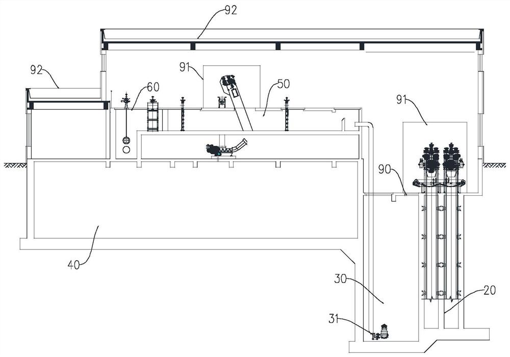
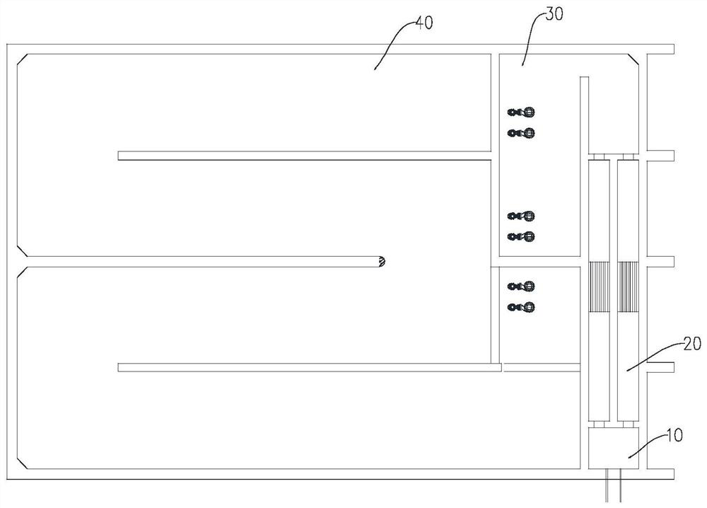
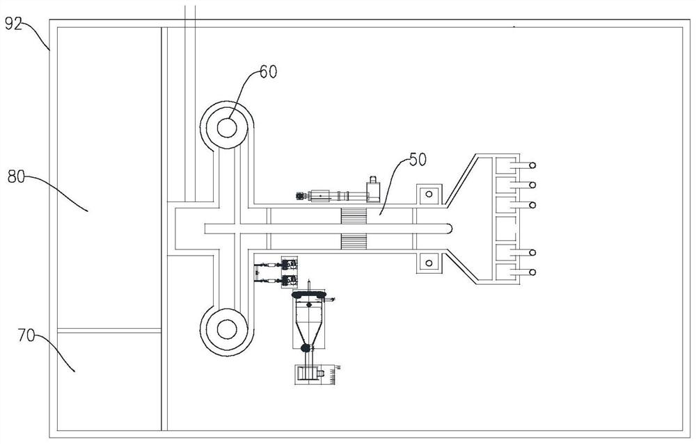
[0036] In the first aspect, the embodiments of the present application provide a combined preprocessing system, please refer to Figure 1 to Figure 4 , the combined pretreatment system includes a coarse grid well 20, a regulating tank 40, a fine grid well 50 and a cyclone grit chamber 60 connected in sequence. The well 20 is provided with a coarse grid for removing impurities and floating objects in the sewage. The coarse grid well 20 is communicated with the regulating pool 40; The grid well 50 is connected, and the fine grid well 50 is provided with a fine grid for removing fine impurities and floating objects in the sewage, and the water outlet end of the fine grid well 50 is connected with the water inlet end of the cyclone grit chamber , the cyclone grit chamber 60 is used for precipitating the gravel in the sewage; wherein, at least two of the coarse grid well 20, the adjustment tank 40, the fine grid well 50 and the cyclone grit chamber 60 are vertically spaced The distributed and combined pretreatment system also includes a power assembly, and the power assembly is used to realize the transmission of sewage in the vertical direction.
[0037] In this solution, the sewage to be treated flows into the coarse grid well 20, and the coarse grid sieves the sewage, removes larger impurities and floating objects, and then flows into the adjustment tank 40, and the adjustment tank 40 performs conditioning treatment on the sewage, Then the conditioned sewage enters the fine grid well 50, the fine grid well 50 can remove the fine impurities and floating objects in the sewage, and the cyclone grit chamber 60 can precipitate the gravel in the sewage, so as to realize the pre-treatment of the sewage. processing, reducing the processing difficulty of the subsequent secondary processing unit. More importantly, by distributing at least two of the coarse grid wells 20, the conditioning tank 40, the fine grid wells 50 and the cyclone grit chambers 60 in the combined pretreatment system in the vertical direction, compared with the As for the existing distributed independent distribution, the area occupied by each processing unit in the combined pretreatment system is saved, which makes the space layout of the combined pretreatment system more reasonable. And the use of power components can realize the transmission of sewage in the vertical direction, so that the combined pretreatment system occupies a smaller area, which is very suitable for sewage treatment with limited floor space, poor site geological conditions and small scale. The preprocessing system of the station is used.
[0038] Wherein, at least two of the coarse grid wells 20 , the adjustment tank 40 , the fine grid wells 50 and the swirling grit chambers 60 are spaced apart in the vertical direction. It can be understood that the coarse grid wells 20 and the adjustment tank 40 , the fine grid well 50 and the cyclone grit chamber 60 can be divided into multi-layer design, for example, can be two or three layers; The flow sand settling tank 60 can be divided into two layers in the vertical direction, or can be divided into three layers in the vertical direction, namely the coarse grid well 20, the adjustment tank 40, the fine grid well 50 and the swirling sand settling. The pools 60 can each be in different planes in the vertical direction.
[0039] It should be noted that the adjustment tank 40 can play a role in balancing the influent water quantity and quality of the sewage, and reducing the variation coefficient of the secondary and advanced treatment design of the sewage.
[0040] Optionally, the fine grid well 50 and the cyclone grit chamber 60 are vertically positioned on a first plane and adjacent to each other, the first plane is located above the ground, and the coarse grid well 20 and the adjustment tank 40 are both located below the ground ; The power assembly includes a first lift pump, the first lift pump is set in the adjustment tank 40, and the first lift pump communicates with the fine grid well 50 of the pipeline.
[0041] By arranging some of the processing units in the combined pretreatment system above the ground and some of the processing units below the ground, that is, reasonably distributed in the vertical direction, compared with the existing distributed and independent distribution of each processing unit, saving The occupied area of ​​each treatment unit in the combined pretreatment system on the horizontal plane makes the space layout of the combined pretreatment system more reasonable, and the sewage in the adjustment tank 40 can be lifted by the first lift pump in the power assembly. To the fine grid well 50 located above the ground, the transmission of sewage in the vertical direction is realized.
[0042] In some embodiments, the conditioning tank 40 is located on a second plane, the coarse grid well 20 and the lifting tank 30 are located on a third plane and adjacent to each other, and the first plane, the second plane and the third plane are in the vertical direction Distributed sequentially from top to bottom; the power assembly also includes a lift pool 30 and a second lift pump 31 located on the third plane, the water outlet end of the coarse grid well 20 is communicated with the lift pool 30, and the second lift pump 31 is provided in the lift pool 30. Inside, the second lift pump 31 communicates with the adjustment tank 40 through a pipeline.
[0043] By subdividing the underground coarse grid well 20, the lifting pool 30 and the regulating pool 40 into two-layer design, that is to say, each processing unit in the combined pretreatment system is divided into a three-layer design, the fine grid well 50 and the rotary The flow grit chamber is located above the ground, the adjustment tank 40 is located on the ground floor, and the coarse grid well 20 and the lifting pool 30 are located on the two underground floors. The second lift pump 31 in the lifting pool 30 can lift the sewage in the lifting pool 30. into the adjustment tank 40, and the first lift pump in the adjustment tank 40 can lift the sewage into the fine grid well 50, so the use of the first lift pump and the second lift pump 31 in the power assembly can realize the sewage in the vertical direction. The transmission and circulation in the direction make the area of ​​the combined pretreatment system smaller, which is very suitable for the pretreatment system of the sewage treatment station with limited floor space, poor site geological conditions and small scale.
[0044] Among them, the coarse grid well 20, the lifting pool 30 and the regulating pool 40 located underground can all be made of steel concrete structure, thereby ensuring the overall structural strength of the coarse grid well 20, the lifting pool 30 and the regulating pool 40, and improving the combination To improve the overall stability of the pretreatment system, there is a house 92 above the ground floor, and the house 92 can cover the fine grid well 50 and the cyclone grit chamber 60 . The coarse grid well 20 is provided with a floor drain 90, the coarse grid grid head is on the adjustment tank 40, and the floor drain 90 can directly discharge the flushing water of the coarse grid into the adjustment tank 40 through a pipeline, saving drainage pipes.
[0045] In some embodiments, the combined pretreatment system further includes a water inlet well 10 located on the third plane, the water inlet well 10 is connected with a sewage pipe, and the water inlet well 10 has a sewage end flowing into the coarse grid well 20 . By providing the water inlet well 10 at the front end of the coarse grid well 20, the water inlet well 10 can play a certain temporary storage role for the sewage flowing out of the sewage pipe, which is convenient for real-time control of the amount of sewage flowing into the coarse grid well 20, so as to ensure the follow-up The effect of pretreatment system on sewage treatment.
[0046] In some embodiments, a gate that can be opened and closed is provided at the discharge end of the water inlet well 10 . By arranging a gate at the discharge end of the intake well 10, the gate is used to control the opening and closing of the discharge end, so that the sewage in the intake well 10 can be controllably flowed into the coarse grid well 20, which facilitates the control of the sewage in the intake well 10. Among them, the gate can use the existing lift gate.
[0047] In some embodiments, the combined pretreatment system further includes a power distribution room 80 for supplying power to the combined pretreatment system, and the power distribution room 80 is located on the first plane. By arranging the power distribution room 80 on the ground, the power distribution room 80 can not only ensure power supply to each processing unit in the combined pretreatment system, but also facilitate the daily maintenance of the power distribution room 80 by the staff.
[0048] Wherein, power distribution equipment is installed in the power distribution room 80, which may include weak current and strong current equipment, so as to realize power supply to the combined pretreatment system.
[0049] In some embodiments, the combined pretreatment system further includes a water quality monitoring room 70. The water quality monitoring room 70 is connected to the inlet end of the coarse grid well 20 to monitor the quality of the sewage from the coarse grid well 20. The water quality monitoring room 70 is located at first plane. By setting the water quality monitoring room 70 at the water inlet end of the coarse grid well 20, the water quality monitoring room 70 can monitor the quality of the sewage in the coarse grid well 20 in real time, so that it is convenient to monitor the quality of the sewage in the pretreatment system according to the water quality of the wastewater. The various treatment units of the equipment are adjusted accordingly so that the water quality of the sewage meets the preset value.
[0050] Among them, the water quality monitoring room 70 may be provided with water quality detection equipment and a control system. For example, the water quality detection equipment may be provided with monitoring equipment such as COD online monitor, ammonia nitrogen online monitor, total phosphorus online monitor, total nitrogen online monitor, etc. The system can control each processing unit in the pretreatment system correspondingly according to the water quality conditions monitored by the water quality testing equipment, so as to realize automatic monitoring and control of sewage water quality.
[0051] In some embodiments, the tops of the coarse grid well 20 and the fine grid well 50 are covered with a deodorizing cover 91, and the deodorizing device communicates with the deodorizing cover for purifying exhaust gas. By arranging the deodorizing cover 91 above the coarse grid well 20 and the fine grid well 50, the deodorizing cover 91 can effectively prevent the odor from overflowing. The odor is discharged to the deodorizing device, and the deodorizing device collects and processes the odor.
[0052] The deodorizing cover 91 is a sealed rectangular cover body made of FRP, and the deodorizing cover 91 is provided with a sealing cover door. The deodorizing cover 91 completely covers the upper opening of the coarse grid well 20 and the fine grid well 50, and the peripheral side of the deodorizing cover 91 is fixed to the installation surface or the ground. The deodorizing device can include deodorizing equipment and a deodorizing fan. The deodorizing equipment can adopt biological deodorizing technology, activated carbon adsorption technology, UV photocatalytic oxidation technology, etc., and the odor or waste gas in each deodorizing hood 91 is extracted through the deodorizing fan. Enter to deodorization equipment. The deodorizing device is a well-known technology in the art, which can be realized by those skilled in the art according to the description of the present application, and will not be repeated here.
[0053] In addition, the deodorizing cover 91 can also be equipped with a grid slag bucket. The grid slag bucket can be made of stainless steel and has corrosion resistance. The coarse grid or fine grid cleans the grid slag from the sewage, and the grid slag falls into the grid. In the slag bucket, it is easy to manage.
[0054] In some embodiments, the inner wall of the pool top of the lift pool 30 is provided with a liquid level gauge linked with the second lift pump 31 . A liquid level gauge is also provided on the inner wall of the pool top of the lift pool 30. Since the level gauge is linked with the second lift pump 31, when the level gauge detects that the amount of sewage in the lift pool 30 reaches a preset value, the first level gauge is activated. The second lift pump 31 loads the sewage into the adjustment tank 40 , which can automatically control the lift tank 30 .
[0055] In the second aspect, the embodiment of the present application provides a treatment method for a combined pretreatment system, including the following steps: S1 : the sewage to be treated flows into the coarse grid well 20 , and the sewage after passing through the coarse grid and coarse screen flows into the adjustment tank 40 S2: The adjusting tank 40 quenches the sewage, and the sewage adjusted by the adjusting tank 40 flows into the fine grille well 50; S3: The fine grille in the fine grille well 50 sieves the sewage finely. The latter sewage flows into the cyclone grit chamber 60, the cyclone grit chamber settles the large particles of sand and gravel in the sewage, and the effluent enters the secondary treatment unit after precipitation.

PUM

no PUM

Description & Claims & Application Information

We can also present the details of the Description, Claims and Application information to help users get a comprehensive understanding of the technical details of the patent, such as background art, summary of invention, brief description of drawings, description of embodiments, and other original content. On the other hand, users can also determine the specific scope of protection of the technology through the list of claims; as well as understand the changes in the life cycle of the technology with the presentation of the patent timeline. Login to view more.
Why Eureka
Try Eureka