Silk thread circular blowing cooling device for textile production

A cooling device and textile technology, applied in textiles and papermaking, filament/thread forming, fiber processing, etc., can solve the problems of weak air flow, spinning dirt and deformation, slow spinning cooling and forming process, etc., to achieve cooling The effect of small molding and low degree of wetting

Pending Publication Date: 2022-08-02
苏州益盟新材料科技有限公司
View PDF0 Cites 0 Cited by
  • Summary
  • Abstract
  • Description
  • Claims
  • Application Information

AI Technical Summary

Problems solved by technology

[0003] In the prior art, when the fibers are formed in the melt spinning, it is necessary to use the ring blowing equipment to cool and solidify the spinning into fibers. The cooling air at the position of the guide ring blowing sleeve at the position of the air duct is due to the distance difference between the exhaust position of the hole on the ring blowing sleeve and the position of the air inlet pipe, so that the position farther away from the air inlet pipe is directed outward. The strength of the blowing airflow is weak, and the cooling effect on the spinning is poor, resulting in uneven cooling of the spinning and affecting the quality of the spinning; during the long-term use of the ring blowing sleeve, the dust and impurities in the airflow are easy to adhere to At the edge of the hole on the ring blowing sleeve, the attached impurities fall under the blowing of the airflow, and are blown to the spinning position with the airflow. The impurities are attached to the outside of the spinning and formed with the cooling of the spinning. Embedded in the inside of the spinning, it will cause the dirt and deformation of the spinning, and affect the quality of the spinning; in the process of generating cooling air in the ring air cooling equipment, the temperature of the cooling air circulation pipe is low, and the temperature difference between the cooling air and the external environment Larger, it is easy to condense and produce water droplets on the inner wall of the circulation pipe, and increase the humidity of the cooling air flowing out of the pipe. When cooling and forming the spinning, it is easy to cause the spinning to be wet, and the cooling and forming process of the spinning is slower. ;

Method used


Image

  • Silk thread circular blowing cooling device for textile production
  • Silk thread circular blowing cooling device for textile production
  • Silk thread circular blowing cooling device for textile production

Examples


Embodiment 1

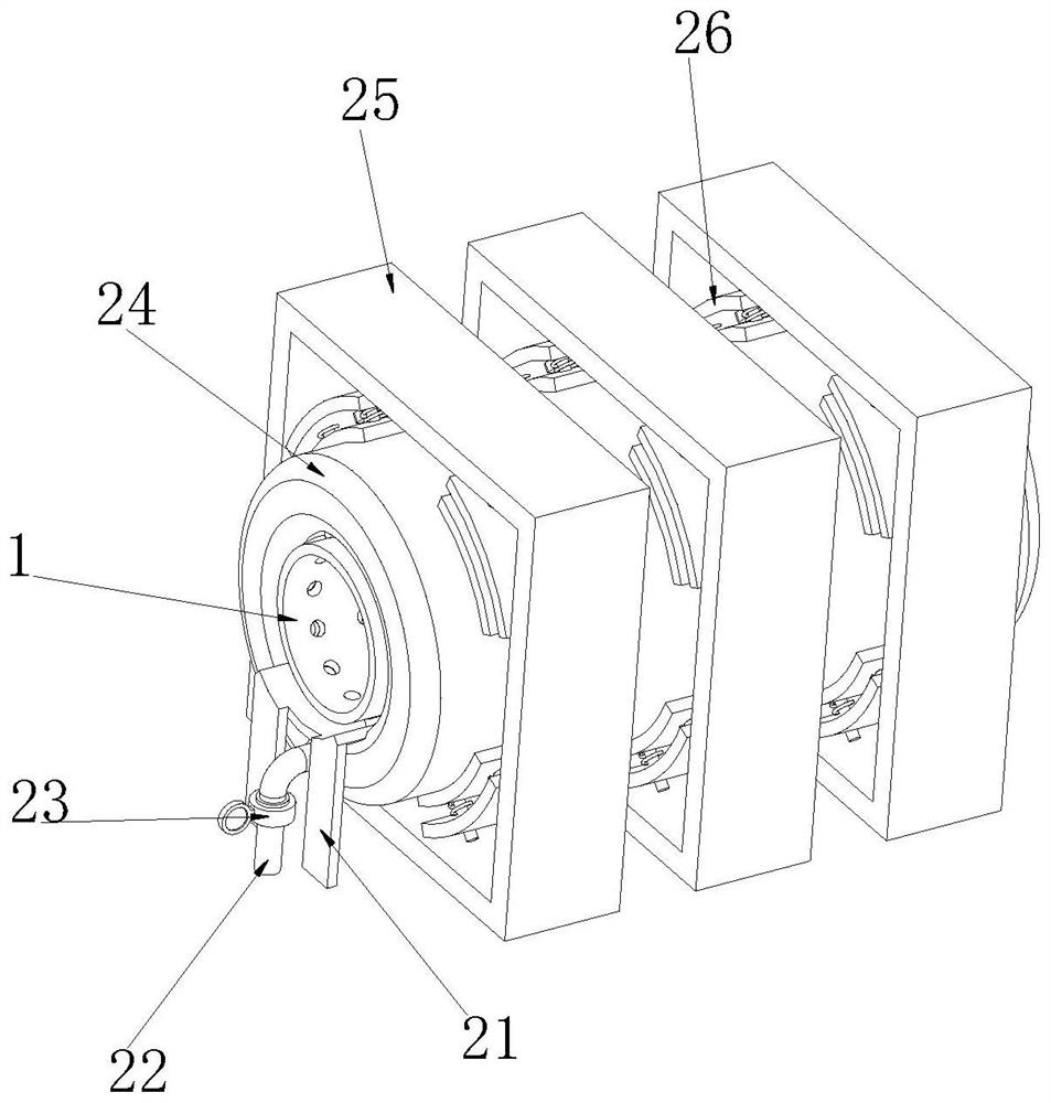
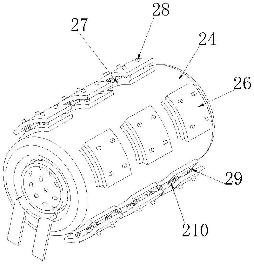
[0029] see Figure 1-2 As shown, a wire ring blowing cooling device for textile production includes a ring blowing sleeve 1, the outer side wall of the ring blowing sleeve 1 is provided with a ring blowing bracket 21, the upper end of the ring blowing bracket 21 is a cylindrical structure, and the lower end is a cylindrical structure. It is a four-leg structure, and the inner diameter of the cylindrical upper end structure is larger than the outer diameter of the ring blowing sleeve 1. The outer side wall of the ring blowing bracket 21 is connected with a rubber air bag 24, and one side of the outer side wall of the ring blowing bracket 21 is connected to the air inlet. Pipe 22, the outer side wall of the air inlet pipe 22 is connected with a first control valve 23, the inner side wall of the ring blowing bracket 21 is connected with a communication pipe at the position of the hole on the outer side wall of the ring blowing sleeve 1, and the outer side wall of the communication...

Embodiment 2

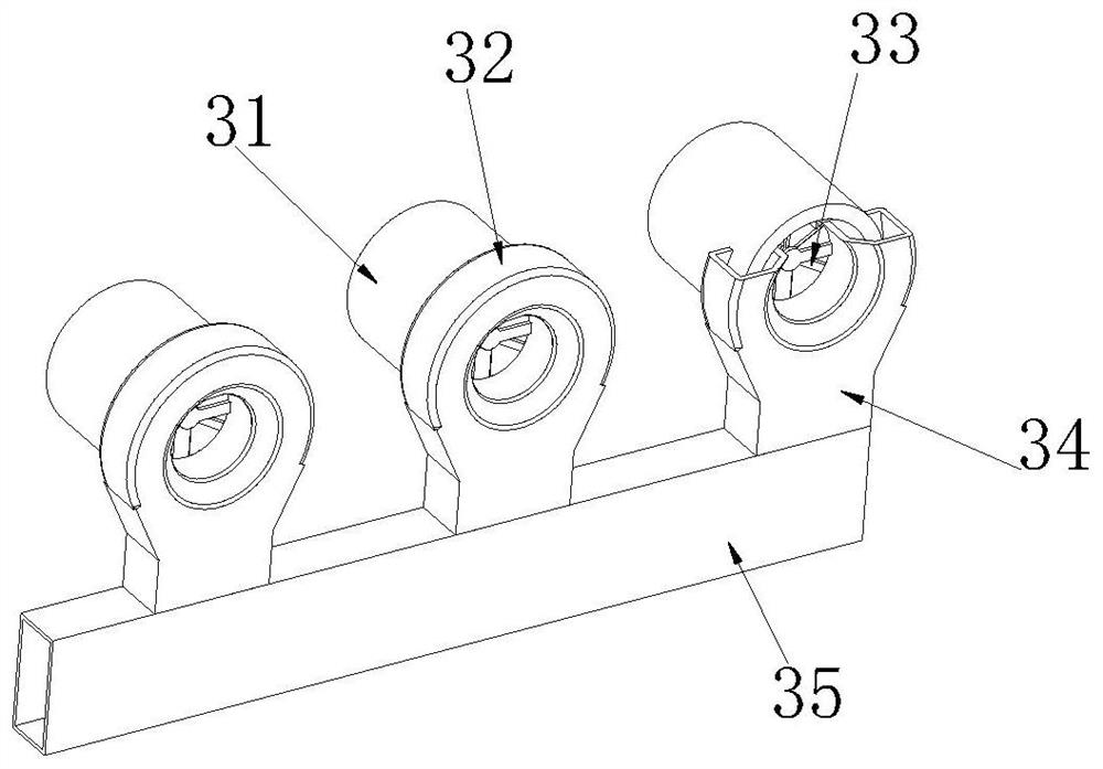
[0033] see Figure 3-4 As shown, the inner side wall of the ring blowing sleeve 1 is connected with an air duct 31 at the position corresponding to the hole, and the end of the air duct 31 away from the ring blowing sleeve 1 is connected with a miscellaneous exhaust sleeve 32, and the outer diameter of the miscellaneous sleeve 32 is larger than that of the air guide. The size of the outer diameter of the pipe 31, the size of the inner diameter is equal to the size of the inner diameter of the air duct 31, the inner wall of the miscellaneous exhaust sleeve 32 is in close contact with the inner wall of the air duct 31, and one side of the outer side wall of the miscellaneous exhaust sleeve 32 is integrally formed. Inside the miscellaneous sleeve 32, one end close to the air duct 31 is connected with a miscellaneous discharge rotating blade 33, the bottom end of the miscellaneous pipe 34 is connected with a miscellaneous discharge pipe 35, and the outer side wall of the miscellane...

Embodiment 3

[0037] see Figure 5-8 As shown, the rubber airbag 24 is provided with a rotating groove 44, the number of rotating grooves 44 is two, and the two rotating grooves 44 are respectively connected on both sides of the ring blowing bracket 21, and the inner side wall of the rotating groove 44 is slidably connected with a rotating frame 43 A connecting plate 45 is connected to the side of the outer side wall of the rotating frame 43 away from the ring blowing bracket 21 , a cleaning sponge is connected to the side of the outer side wall of the connecting plate 45 that is close to the rubber airbag 24 , and the side of the outer side wall of the rotating frame 43 that is close to the air inlet duct 22 An interlocking groove 42 is integrally formed, the inner side wall of the ring blowing bracket 21 is connected with a rotating bracket 46 at the position corresponding to the interlocking groove 42, and the middle position of the outer side wall of the rotating bracket 46 is rotatably ...


PUM


Abstract

The invention relates to a silk thread annular blowing cooling technology, aims to solve the problem that spinning is difficult to cool and form quickly due to the fact that cooling air is not uniform, impurities exist in airflow and the humidity in the airflow is high, and particularly relates to a silk thread annular blowing cooling device for textile production, the silk thread annular blowing cooling device comprises an annular blowing sleeve, and an annular blowing support is arranged on the outer side wall of the annular blowing sleeve; cooling air generated by the circular blowing cooling equipment is collected through the rubber air bag and then released, so that the blowing strength of airflow at all positions is the same, the spinning can be uniformly cooled, impurity removal rotating blades are driven by circulating airflow in the air guide pipe to rotate, and the spinning quality is improved. Impurities cleaned by an impurity scraping knife on an impurity discharging rotating blade are driven by airflow, the impurities cannot reach the spinning position along with the airflow, adverse effects on the spinning quality are avoided, the linkage rotating blade is driven by the airflow circulating at the air inlet pipe to rotate, the wetting degree of cooling air blown out from the interior of the rubber air bag is low, and the spinning quality is improved. And the influence on cooling forming of spinning is small.

Description

technical field [0001] The invention relates to a wire ring blowing cooling technology, in particular to a wire ring blowing cooling device for textile production. Background technique [0002] Ring blowing is one of the cooling blowing methods during fiber formation in melt spinning. The cooling air blows from the circumferential direction to the thin stream of melt ejected from the spinneret hole, so that the thin stream is uniformly cooled and solidified into fiber, which is suitable for spinning Spinning cooling when the number of holes is large; [0003] In the prior art, when the fibers are formed in melt spinning, a ring blowing device is used to cool and solidify the spinning into fibers, and the cooling air blows the spinning at the inner center of the ring blowing sleeve from all directions. The cooling air at the position of the guide ring blowing sleeve at the position of the air duct is caused by the difference in the distance between the exhaust position of th...

Claims


Application Information

Patent Timeline
IPC IPC(8): D01D5/092
CPCD01D5/092Y02P70/62
Inventor 吴振林唐良孙琪王艳丹
Owner 苏州益盟新材料科技有限公司
Why Eureka
Try Eureka