Eureka AIR delivers breakthrough ideas for toughest innovation challenges, trusted by R&D personnel around the world.

Sensing system based on RFID and time reversal electromagnetism

A time-reversal and sensing system technology, applied in the field of sensing, can solve problems such as unfavorable sensor reading, low temporal and spatial resolution, and limited number of sensors, and achieve high information retention, high energy utilization, and high spatial resolution rate effect

Active Publication Date: 2022-08-02
UNIV OF ELECTRONICS SCI & TECH OF CHINA
View PDF9 Cites 0 Cited by
  • Summary
  • Abstract
  • Description
  • Claims
  • Application Information

AI Technical Summary

Problems solved by technology

When RFID technology is applied in the sensing system, the former method of distinguishing different sensors greatly limits the number of sensors, or requires personnel to hold the receiving end to read each sensor one by one.
The latter will lose part of the information during the signal decomposition process, which is not conducive to the sensor to read all the information, and at the same time the spatial and temporal resolution is low, so that the placement distance between the sensors is limited

Method used


Image

  • Sensing system based on RFID and time reversal electromagnetism
  • Sensing system based on RFID and time reversal electromagnetism
  • Sensing system based on RFID and time reversal electromagnetism

Examples


Embodiment 1

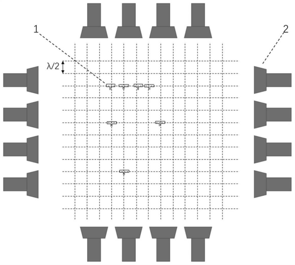
[0030] This embodiment provides a sensing system based on RFID and time-reversal electromagnetics, the structure is as follows figure 1 As shown, it includes a sensor array and a plurality of TRM transceiver integrated units 2 located around the sensor array, and each TRM transceiver integrated unit 2 together forms a sensor reading system around the sensor array. The sensor array is composed of a plurality of RFID antenna sensors 1 arranged in an array, each RFID antenna sensor 1 corresponds to a spatial position, and the minimum distance between adjacent RFID antenna sensors 1 is 0.16-0.18m.

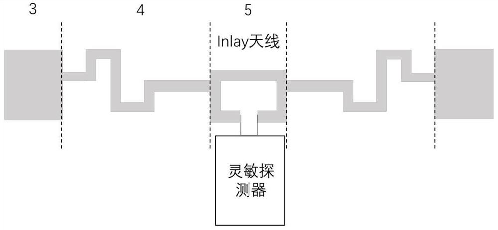
[0031] The RFID antenna sensor 1 includes a connected Inlay antenna and a sensitive detector, such as figure 2 shown. The Inlay antenna is a symmetrical structure, including a ring matching section 5, a bent dipole antenna section 4 and an end loading impedance 3 located at both ends of the ring matching section 5 in turn, and the open end of the ring matching section 5 and the sensi...


PUM


Abstract

The invention discloses a sensing system based on RFID and time reversal electromagnetism, and belongs to the technical field of sensing, the sensing system comprises a plurality of RFID antenna sensors arranged in an array and a plurality of TRM transmit-receive integrated units around the RFID antenna sensors, each RFID antenna sensor corresponds to a spatial position, and simulation time reversal signals of all spatial positions are stored in the RFID antenna sensors; for a to-be-measured spatial position, each TRM transmit-receive integrated unit processes a corresponding simulation time inversion signal, after emission, the simulation time inversion signal converges into a Gaussian pulse electromagnetic wave signal at the to-be-measured spatial position, an RFID antenna sensor at the to-be-measured spatial position reflects an antenna reflection electromagnetic wave containing current environment position information, and after real-time processing by each TRM transmit-receive integrated unit, the Gaussian pulse electromagnetic wave signal is transmitted to the to-be-measured spatial position. And obtaining the environment change of the to-be-measured spatial position. According to the invention, the sensor at any position in the space can be read in real time, so that the environment information is obtained, and the method has the characteristics of high information retention degree, high spatial resolution and high energy utilization rate.

Description

technical field [0001] The invention belongs to the field of sensing technology, in particular to a sensing system based on RFID and time-reversal electromagnetics. Background technique [0002] At present, various sensing systems connect sensing devices in various ways to complete information interaction, and realize functions such as intelligent monitoring, control, identification, positioning, and tracking. However, traditional sensing devices are mostly active wired sensors, which face problems such as large size, need to replace batteries later, difficult maintenance, and limited placement environment. Passive detectors based on Radio Frequency Identification (RFID) can solve the above problems and are the core technology for realizing passive wireless sensor systems. [0003] Through RFID technology, the information of a single sensor can be easily read, and it is used in various identification target scenarios such as cargo monitoring, cold chain transportation, and ...

Claims


Application Information

Patent Timeline
Patent Type & Authority Applications(China)
IPC IPC(8): G06K7/08
CPCG06K7/087Y02D30/70
Inventor 李荐育徐浩巫江辛雅轩王子晨邹吉化皇甫学丰胡锐冰
Owner UNIV OF ELECTRONICS SCI & TECH OF CHINA
Why Eureka
Eureka Blog
Learn More