
Magnetic brain scanning equipment

A scanning device and magnetoencephalography technology, applied in the field of magnetoencephalography, can solve problems such as magnetic field signal noise, and achieve the effect of avoiding magnetic noise, ensuring accuracy, and good accuracy

Active Publication Date: 2022-08-05
BEIJING QUANMAG HEALTHCARE CO LTD
View PDF8 Cites 0 Cited by
  • Summary
  • Abstract
  • Description
  • Claims
  • Application Information

AI Technical Summary

Problems solved by technology

[0005] In view of this, in order to solve the above-mentioned existing problems, the embodiment of the present invention provides a magnetic brain scanning device, by adding a fixed member to the guide rail member of the scanning bed device, and then setting the guide rail member independently of the magnetic shielding cylinder, Avoid the technical problem of the magnetic field signal noise caused by the vibration of the guide rail components being transmitted to the magnetic shielding cylinder

Method used


Image

  • Magnetic brain scanning equipment
  • Magnetic brain scanning equipment
  • Magnetic brain scanning equipment

Examples


Embodiment 1

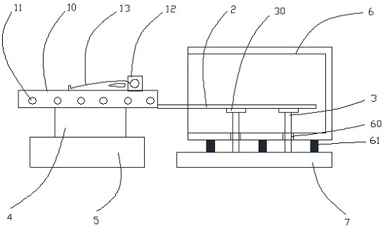
[0033] Please refer to figure 1 A schematic structural diagram of a magnetic brain scanning device shown in this embodiment, a magnetic brain scanning device in this embodiment, the magnetic brain scanning device includes a scanning bed device and a magnetic shielding device, wherein the scanning bed device includes a bed body mechanism, a guide rail. Member 2 and a fixing member 3 for fixing the guide rail member 2; the magnetic shielding device comprises a magnetic shielding cylinder 6 and a fixing base 7 for fixing the magnetic shielding cylinder 6; It is connected to the bed mechanism, and the other end extends into the magnetic shielding cylinder 6 . The magnetic shielding cylinder 6 is provided with a hole 60 , and the fixing member 3 passes through the hole 60 and abuts on the fixing base 7 .

[0034] It should be noted that the magnetic shielding cylinder in this embodiment is used to shield the external magnetic field, and the magnetic shielding cylinder is fixedly co...

Embodiment 2

[0039] combine figure 1 , figure 2 As shown, this embodiment is based on Embodiment 1. As a preferred implementation manner, the bed mechanism in this embodiment further includes a collection box 5 and a control box 4 arranged below the bed board body 10 , Among them, an isolation plate is arranged between the acquisition box 5 and the control box 4, so that the two boxes are separately arranged and designed to avoid mutual magnetic field interference between the scanning bed control circuit and the acquisition circuit.

[0040] As a preferred embodiment, the outer shells of the collection box 5 and the control box 4 in this embodiment are preferably, but not limited to, aluminum alloys. The shell permeability μ is much larger than the air permeability μ, so most of the magnetic field lines pass through the wall of the shell, and there are very few magnetic field lines in the cavity inside the shell, so as to achieve high-frequency shielding. The purpose of electromagnetic ...

Embodiment 3

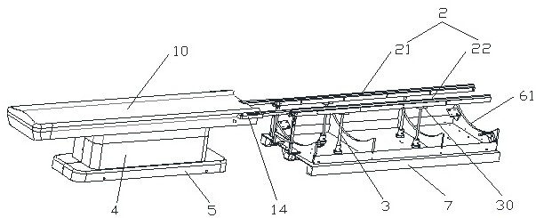
[0045] combine figure 2 As shown, this embodiment is based on Embodiment 1 and Embodiment 2. As a preferred implementation, the guide rail member 2 in this embodiment includes a first rail 21 and a second rail 22, and the two rails are mutually parallel. A plurality of rollers 11 installed on the bottom wall of the bed base body 10 that are adapted to the first track and the second track roll on the two tracks, so that the bed base body can move more smoothly.

[0046] As a preferred embodiment, the fixing member 3 in this embodiment is preferably, but not limited to, four support columns, and can also be set to other numbers of support columns, such as six, eight, etc., according to the actual situation. There are two symmetrical support columns on each guide rail, that is, one end of the first support column and the second support column are fixedly connected to the first rail 21, and the other end is fixedly connected to the fixed base 7 through the hole 60; the third sup...


PUM


Abstract

The invention provides brain magnetic scanning equipment. The brain magnetic scanning equipment comprises a scanning bed device, a magnetic shielding device, a brain magnetic detector installed on the scanning bed device and a magnetic stabilization configuration facilitating detection of brain magnetic signals by the brain magnetic detector. The scanning bed device comprises a bed body mechanism, a guide rail component and a fixing component used for fixing the guide rail component. The magnetic shielding device comprises a magnetic shielding cylinder and a fixing base used for fixing the magnetic shielding cylinder. Wherein one end of the guide rail component abuts against the bed body mechanism, the other end of the guide rail component extends into the magnetic shielding cylinder, a hole is formed in the magnetic shielding cylinder, and the fixing component penetrates through the hole to abut against the fixing base. According to the brain magnetic scanning equipment, the guide rail component is independent of the magnetic shielding cylinder, vibration of the guide rail component is prevented from being transmitted to the magnetic shielding cylinder, the stability of brain magnetic acquisition signals is greatly improved, and then the brain magnetic measurement accuracy can be better guaranteed.

Description

technical field [0001] The invention relates to the technical field of magnetoencephalography, in particular to a magnetoencephalography scanning device. Background technique [0002] Magnetoencephalography (MEG) is a non-invasive functional brain imaging method that infers neuronal activity inside the brain by measuring the magnetic field generated by neural currents outside the head. Magnetoencephalography has ultra-high temporal and spatial resolution. , plays an important role in the lesion diagnosis of neurological and psychiatric diseases and cognitive neuroscience research. [0003] The strength of the brain magnetic field is very weak, and it is very sensitive to minimal interference from the outside world. Especially in the magnetic brain scanning equipment in the prior art, the bed board body carrying the subject follows the track fixed on the inner wall of the magnetic shielding cylinder. When moving, or the subject's body moves slightly, vibrations are inevitabl...

Claims


Application Information

Patent Timeline
IPC IPC(8): A61B5/245A61B5/00
CPCA61B5/245A61B5/702A61B5/4088
Inventor 盛经纬
Owner BEIJING QUANMAG HEALTHCARE CO LTD
Learn More