Eureka AIR delivers breakthrough ideas for toughest innovation challenges, trusted by R&D personnel around the world.

Hemostatic stent for heart great vessel surgery

A technology for large blood vessels and surgery, which is applied in the field of hemostatic stents for cardiac and large blood vessel surgery, can solve the problems of increased surgical risk, increased blood loss, and long operation time, and achieves the advantages of increasing surgical risk, improving adaptability, and increasing blood loss. Effect

Pending Publication Date: 2022-08-05
王建林
View PDF0 Cites 0 Cited by
  • Summary
  • Abstract
  • Description
  • Claims
  • Application Information

AI Technical Summary

Problems solved by technology

[0002] Cardiac and great vessel surgery is a general term for surgical treatment methods for aortic trunk diseases (Marfan syndrome, aortic dissection, etc.), and has always been a huge, complex, difficult, and high-risk surgery in cardiovascular surgery. There are not many cardiovascular centers that independently perform large vessel surgery. The risk of large vessel surgery is high, the mortality rate is high, and the operation time is long. Generally, only a few major heart centers in the country are competent for this operation.
[0003] In the process of heart and great vessel surgery, aortic clamp is routinely used to clamp a certain segment of arterial vessel, so that the adjacent blood vessels at the clamped site can be opened for surgical operation. If it is opened, it will cause certain damage to the outer wall of the aortic vessel, and when the aortic clamp is released, a large amount of blood will be ejected from the aorta, which increases the blood loss during the operation, affects the surgical field of view, and also increases the surgical risk

Method used


Image

  • Hemostatic stent for heart great vessel surgery
  • Hemostatic stent for heart great vessel surgery
  • Hemostatic stent for heart great vessel surgery

Examples


Embodiment approach

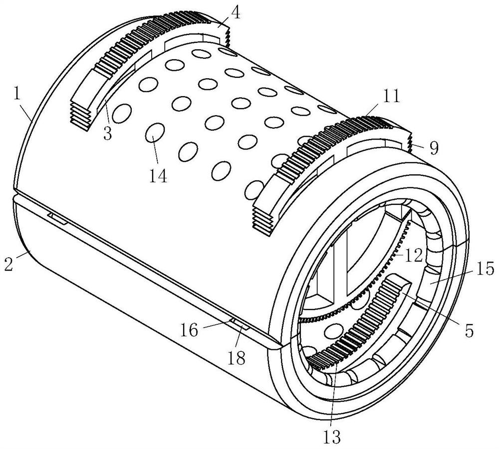
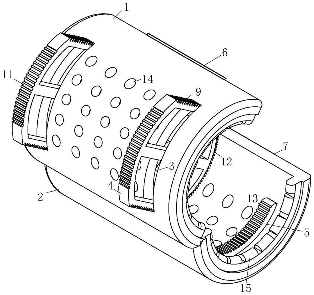
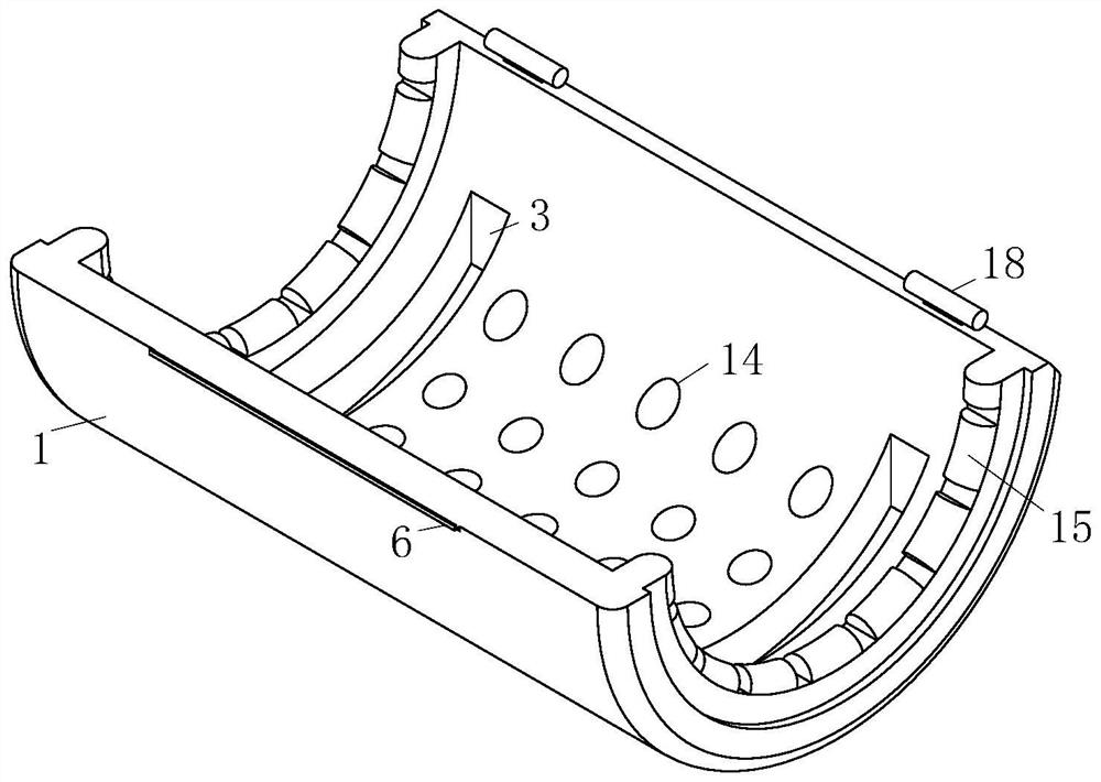
[0050] As an embodiment of the present invention, the clamping assembly includes:

[0051] Slot 3, two described slots 3 are symmetrically opened on one side of No. 1 housing 1;

[0052] Push plates 4, two of the push plates 4 are respectively installed in the two slots 3;

[0053] The clip seat 5, two of the clip seats 5 are symmetrically installed on the inner side of the second housing 2;

[0054] Buckle 6, said buckle 6 is L-shaped and installed on one side of No. 1 housing 1;

[0055] A blocking block 7, the blocking block 7 is fan-shaped and installed on one side of the No. 2 housing 2;

[0056] Before the aorta is clamped, the No. 1 casing 1 and No. 2 casing 2 are relatively opened by using the connecting assembly, and the opening height formed by opening No. 1 casing 1 and No. 2 casing 2 is greater than the cross-sectional diameter of the aorta. , so the aorta can enter the middle position of No. 1 shell 1 and No. 2 shell 2 through the open opening. At this time, th...


PUM


Abstract

The invention relates to the technical field of medical apparatus and instruments, in particular to a hemostatic stent for heart great vessel surgery, which is characterized in that a first shell and a second shell can be relatively closed and opened by using a connecting assembly, so that when aorta is clamped and sealed, the first shell and the second shell can be relatively closed and opened; the first shell and the second shell which are oppositely opened are smoothly arranged at any position of an arterial canal in a sleeving mode through the opened opening, installation of the clamping and sealing assemblies on the aorta is conveniently completed, in addition, the two clamping and sealing assemblies are arranged on the first shell and the second shell at the same time, alternate clamping can be conveniently achieved during aorta clamping and sealing hemostasis, and the clamping and sealing efficiency is improved. The problems that in the long-time operation process, if the clamping and sealing assembly is not loosened frequently, the outer wall of the aorta blood vessel is damaged to a certain degree, once the clamping and sealing assembly is loosened, the aorta sprays a large amount of blood, the blood loss amount in the operation is increased, the operation view is affected, and meanwhile the operation risk is increased are effectively avoided.

Description

technical field [0001] The invention relates to the technical field of medical devices, in particular to a hemostatic stent for cardiac major blood vessel surgery. Background technique [0002] Cardiac major vascular surgery is a general term for the surgical treatment of main aortic diseases (Marfan syndrome, aortic dissection, etc.) There are not many cardiovascular centers that perform major vascular surgery independently. The risk of major vascular surgery is high, the operative mortality rate is high, and the operation time is long. Generally, only a few major heart centers in the country are competent for this operation. [0003] In the process of cardiac major vascular surgery, aortic clamps are routinely used to clamp a certain segment of arterial blood vessels, so that the adjacent blood vessels at the clamping site can be opened for surgical operations. However, aortic clamps are often loosened during long-term operations When the aortic clamp is opened, it will c...

Claims


Application Information

Patent Timeline
IPC IPC(8): A61B17/12
CPCA61B17/12A61B2017/12004
Inventor 王建林秦杰
Owner 王建林
Why Eureka
Eureka Blog
Learn More