Integrated busbar fireproof plate and battery pack

A busbar and fireproof board technology, applied in the field of battery systems, can solve the problems of complex manufacturing process and structure, low thermal runaway resistance, large space occupation, etc., to improve energy density and space utilization, compact structure, and space occupation. small effect

Pending Publication Date: 2022-08-05
FARASIS TECH (GANZHOU) CO LTD +1
View PDF5 Cites 0 Cited by
  • Summary
  • Abstract
  • Description
  • Claims
  • Application Information

AI Technical Summary

Problems solved by technology

However, the existing battery cell horizontal placement scheme generally sets the fireproof board and the bus bar separately, which has many workpieces, takes up a large space, has low ability to prevent thermal runaway, and the manufacturing process and structure are relatively complicated.

Method used


Image

  • Integrated busbar fireproof plate and battery pack
  • Integrated busbar fireproof plate and battery pack
  • Integrated busbar fireproof plate and battery pack

Examples


Embodiment 1

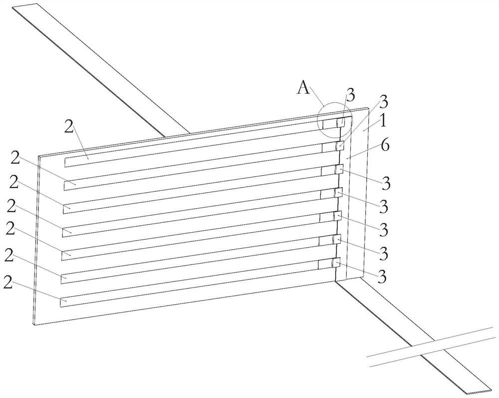
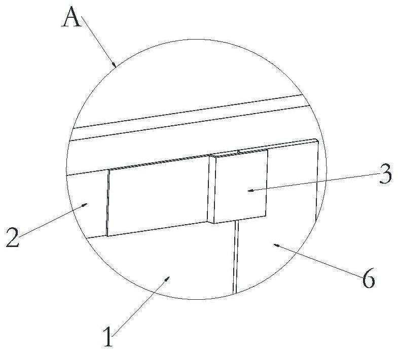
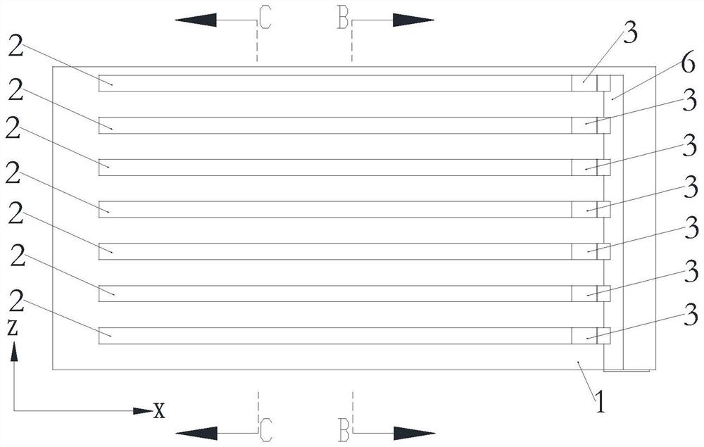
[0080] like Figure 1 to Figure 5 As shown, a fireproof board integrated with busbars in this embodiment includes a fireproof board body 1 and a busbar 2. The fireproof board body 1 is integrally assembled with one or more busbars 2. The busbars 2 has a tab connection surface for connecting the cell tabs 51 ; that is, the tab connection surface of the bus bar 2 is exposed or protruded from the fireproof board body 1 and is used for connecting the cell tabs 51 .

[0081] like Figure 1 to Figure 5 As shown, the bus bar 2 of this embodiment is embedded in the fireproof board body 1, and the surface of the fireproof board body is provided with a tab connecting surface of the busbar to be exposed from the fireproof board body or Protruding cutout 11. The integration between the bus bar 2 and the fireproof board body 1 may adopt the structural form in which the busbar 2 is embedded in the fireproof board body 1, so as to make the structure compact and provide effective and stable...

specific Embodiment approach 1

[0084] Embodiment 1: The fireproof board body 1 is a multi-layer board pressing structure, and the bus bar 2 is pressed and embedded between two adjacent layer board structures; for example, two-layer boards can be used, and each layer board A placement slot for placing the bus bar 2 is opened, and a hollow 11 for at least a part of the surface of the bus bar 2 to be exposed at the bottom of the slot is opened, and then the two layers of boards are pressed into a whole by the equipment, so that the bus bar 2 is clamped Set inlaid between two layers of boards. Of course, for consideration of other processes or structures, more than three layers of plates can also be used for pressing, as long as the inlay of the bus bars 2 and the exposure of the surfaces of the bus bars can be satisfied.

specific Embodiment approach 2

[0085] Embodiment 2: The fireproof board body 1 is a multi-layer laminated structure, the bus bar 2 is sandwiched between two adjacent two-layer laminated structures, and / or between the multi-layer laminated structures The multi-layer board stacking structure and the bus bar 2 are connected and fixed by connecting pieces, that is, the multi-layer board stacking structure can be fixed by connecting pieces, or the multi-layer board structure and the bus bar 2 can be connected. The multi-layer board stacking structure can also be fixed by the first connector, and then the multi-layer board structure and the bus bar 2 can be fixed by the second connector, as long as the bus bar 2 can be stabilized It can be sandwiched between adjacent two-layer board structures. For example, two layers of boards can be used, and a placement slot for placing the bus bar 2 is provided on each layer, and a hollow 11 for exposing at least a part of the surface of the bus bar 2 is provided at the botto...


PUM


Abstract

The invention relates to a fireproof plate integrated with a busbar and a battery pack, the fireproof plate integrated with the busbar comprises a fireproof plate body and the busbar, the busbar is integrally assembled on the fireproof plate body, and at least one part of the surface of the busbar is exposed from the fireproof plate body and is used for connecting a battery cell tab. According to the fireproof plate disclosed by the invention, the busbars are integrated on the fireproof plate, and when the fireproof plate is used, the battery cell tabs on which the battery cells are laid can be directly welded on the busbars of the fireproof plate body, so that the electric connection between the battery cells is realized. According to the module-free battery pack, the busbars are integrated on the fireproof plates, so that parts are reduced, the assembly process is simplified, the structure is simple, the assembled module-free battery pack is compact in internal structure and good in stability, the internal space of the battery pack is saved, and the battery pack is high in energy density and good in safety performance; the light weight of the battery pack is realized, and the automation degree is high.

Description

technical field [0001] The invention relates to the technical field of battery systems, in particular to an integrated busbar fireproof board and a battery pack. Background technique [0002] At present, the soft pack battery system on the market is mainly divided into two forms: Form 1: The battery module is placed in the battery system, and then the battery modules are connected in series and the system components are added to form the entire battery system. This type of battery system needs to form modules outside first, so the production process is more complicated and the work station is relatively long; the battery is made into modules, and then the modules are connected in series, which makes the structure of the entire battery system complex with many components. , the cost of parts and materials is high; there are many parts and a lot of space, so the volume energy ratio of this method has been difficult to improve, and the energy density is low. Form 2: The soft-p...

Claims


Application Information

Patent Timeline
Patent Type & Authority Applications(China)
IPC IPC(8): A62C3/16A62C2/04H01M50/507H01M50/503H01M50/528H01M50/516H01M50/533H01M10/658H01M50/293H01M10/653H01M10/48
CPCA62C3/16A62C2/04H01M50/507H01M50/503H01M50/528H01M50/516H01M50/533H01M10/658H01M50/293H01M10/653H01M10/48Y02E60/10
Inventor 郭伟华邬亨英谈伟刘复平
Owner FARASIS TECH (GANZHOU) CO LTD
Why Eureka
Try Eureka