Water sample pretreatment filtering device for environmental monitoring laboratory

A technology for sample pretreatment and filtration device, applied in the field of environmental monitoring experiments, can solve the problems of easy clogging, decreased fluidity of water samples in the filter plate, and reduced filtering effect of other impurities in water samples, so as to avoid clogging of impurities and improve the The effect of filtering, the effect of improving the time of contact

Pending Publication Date: 2022-08-05
陕西省环境监测中心站
0 Cites 0 Cited by

AI-Extracted Technical Summary

Problems solved by technology

[0002] Environmental monitoring is to determine the status of environmental pollution and the level of environmental quality by monitoring and measuring indicators reflecting environmental quality. Environmental monitoring includes the detection of water samples. Water samples are filtered to remove impurities that affect water quality testing to ensure the accuracy of water sample testing. However, when the treatment and filtration device processes and filters water samples, there are mixed ferromagnetic impurities in the water sample, and the treatment an...

Method used

In the present invention, by water pump 5, the water sample of water storage tank 8 inside is pumped to filter box 65 inner upper end and carries out filtering work, and after water sample enters filter box 65 inner upper end, carries out downward by guide plate 68z to water sample Guide the flow, start the motor 62 at the same time to make the drive rod 68c rotate, through the transmission of the belt 68n, at this time, the three magnetic bar mechanisms 68v rotate synchronously on the inside of the guide plate 68z, and the magnetic bar mechanisms 68v are in contact with the water sample flowing down , during the contact process, the water sample flows from the water inlet hole v9 into the inside of the rotating shell v2, at this time, the magnetic rod v5 magnetically adsorbs the ferromagnetic impurities in the water sample, thereby removing the ferromagnetic impurities in the water sample. The final water sample is then discharged from the water inlet v9 and continues to flow downward, and enters the interior of the flow cell f5 to contact the top plate f7, and the top plate f7 is pressed down by gravity through the water sample. At this time, the top spring f9 at the lower end of the top plate f7 is facing the top plate f7 exerts a reverse elastic force, so that the water sample is ejected back and forth, increasing the contact time between the water sample and the magnetic bar mechanism 68v, and improving the effect of removing ferromagnetic impurities in the water sample.
Wherein, described adsorption mechanism 68 comprises guide plate 68z, driving rod 68c, belt 68n, magnetic rod mechanism 68v, ejection mechanism 68f, and described guide plate 68z is located at filter box 65 inner upper end, and driving rod 68c follows The output end of the motor 62 rotates synchronously, and the drive rod 68c is mounted on the inner middle end of the guide plate 68z by using clearance fit. The rod mechanism 68v is install...

Abstract

The invention discloses a water sample pretreatment filtering device for an environmental monitoring laboratory, the water sample pretreatment filtering device structurally comprises a water storage tank, a water pump, a water pumping pipe, a filtering device and supporting legs, the upper end of the water storage tank and the right lower end of the water pumping pipe are fixedly mounted in an embedded manner and are communicated with each other, the water pump is mounted at the right lower end of the water pumping pipe, and a magnetic rod magnetically adsorbs ferromagnetic impurities in a water sample; the water sample presses down the top plate under the action of gravity, and the top spring applies reverse elastic force to the top plate, so that the water sample flows back and is ejected upwards, and the effect of removing the ferromagnetic impurities in the water sample is improved; in the swinging process of the outer frame, sliding shafts at the left outer side end and the right outer side end of the outer frame perform arc-shaped guiding swinging in sliding grooves, springs apply repeated elastic force to the sliding shafts, two filtering plates in the outer frame perform ejection filtering on a water sample flowing downwards, and the filtering effect of the filtering plates on other impurities in the water sample is improved; meanwhile, impurities are prevented from being blocked in filter holes of the filter plate.

Application Domain

General water supply conservationPreparing sample for investigation +5

Technology Topic

Environmental chemistryWater storage tank +6

Image

  • Water sample pretreatment filtering device for environmental monitoring laboratory
  • Water sample pretreatment filtering device for environmental monitoring laboratory
  • Water sample pretreatment filtering device for environmental monitoring laboratory

Examples

  • Experimental program(2)

Example Embodiment

[0021] Example 1:
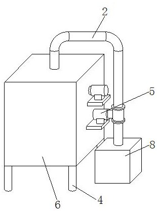
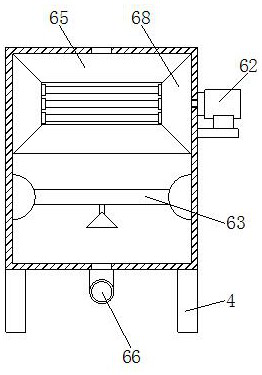
[0022] as attached figure 1 to the attached Figure 5 shown:
[0023] The present invention is a water sample pretreatment and filtering device for environmental monitoring laboratory. The water pump 5 is installed on the lower right end of the suction pipe 2, and the upper left end of the suction pipe 2 is installed on the top of the filter device 6 and communicates with each other. The four corners of the filter device 6 are welded with supporting feet 4. The filter device 6 includes a filter box 65, a motor 62, an adsorption mechanism 68, a filter plate mechanism 63, and a drain pipe 66. The upper left end of the suction pipe 2 is installed on the top of the filter box 65 and communicates with each other. There is a motor 62, and the output end of the motor 62 is connected with the internal drive of the adsorption mechanism 68. The adsorption mechanism 68 is installed on the upper end of the inner side of the filter box 65. The four corners of the bottom of the filter box 65 are welded with support feet 4, and the lower end of the inner side of the filter box 65. A filter plate mechanism 63 is provided, and the filter plate mechanism 63 is located below the adsorption mechanism 68 , and a drain pipe 66 is embedded in the middle end of the bottom of the filter box 65 and communicates with each other.
[0024] The adsorption mechanism 68 includes a guide plate 68z, a drive rod 68c, a belt 68n, a magnetic rod mechanism 68v, and an ejection mechanism 68f. The guide plate 68z is provided at the inner upper end of the filter box 65, and the drive rod 68c outputs along with the motor 62. The driving rod 68c is installed at the inner middle end of the guide plate 68z by clearance fit, the driving rod 68c is connected with the belt 68n in a driving manner, and the driving rod 68c rotates synchronously with the magnetic rod mechanism 68v, and the magnetic rod mechanism 68v It is installed at the inner middle end of the guide plate 68z, and the magnetic rod mechanism 68v is located above the ejection mechanism 68f. The ejection mechanism 68f is fixedly installed on the inner bottom of the guide plate 68z. The ejection mechanism 68f is located above the filter plate mechanism 63. The magnetic rod There are three mechanisms 68v in total, and they are vertically equidistantly distributed at the inner middle end of the guide plate 68z, and the magnetic rod mechanism 68v is connected by a belt 68n to ensure that the three magnetic rod mechanisms 68v rotate synchronously and improve the accuracy of the water sample. The effect of adsorption and removal of ferromagnetic impurities.
[0025] The magnetic rod mechanism 68v includes a rotating casing v2, a water inlet v9, and a magnetic rod v5. The rotating casing v2 rotates synchronously with the driving rod 68c, and a water inlet v9 is embedded in the outside of the rotating casing v2, and rotates The inner middle end of the shell v2 is provided with a magnetic rod v5, the rotating shell v2 is installed on the inner middle end of the guide plate 68z, and the rotating shell v2 is located above the ejection mechanism 68f, and the water inlet v9 has a cavity structure with a wide inlet and a narrow outlet. , which is beneficial to guide the water sample into the rotating shell v2 and make contact with the magnetic rod v5, so that the magnetic rod v5 can effectively magnetically attract the ferromagnetic impurities in the water sample, and the water sample after the magnetic suction will be removed from the water again. The inside of the hole v9 is guided and discharged.
[0026] The ejection mechanism 68f includes a flow groove f5, a drainage hole f2, a top spring f9, and a top plate f7. The flow groove f5 is fixedly installed on the inner bottom of the guide plate 68z, and the flow groove f5 is located under the rotating shell v2. A drainage hole f2 runs through the bottom of the groove f5, and the bottom of the flow groove f5 and the inner side are welded to the lower end of the top spring f9, the upper end of the top spring f9 is welded to the bottom of the top plate f7, and the top plate f7 is located at the inner upper end of the flow groove f5. There are three springs f9 and top plate f7, and the top plate f7 has a wavy structure, which is conducive to the upward and reverse ejection of the water sample flowing down, thereby improving the contact time between the water sample and the magnetic rod mechanism 68v, and improving the water sample. The effect of removing ferromagnetic impurities in the sample.
[0027] The specific usage mode and function of this embodiment:
[0028]In the present invention, the water sample inside the water storage tank 8 is pumped to the upper end of the filter box 65 by the water pump 5 for filtration. After the water sample enters the upper end of the filter box 65, the water sample is guided downward through the guide plate 68z. At the same time, the motor 62 is activated to make the driving rod 68c rotate, and through the transmission of the belt 68n, the three magnetic rod mechanisms 68v rotate synchronously on the inside of the guide plate 68z, and the magnetic rod mechanisms 68v are in contact with the water sample flowing downward. During the process, the water sample flows into the rotating shell v2 from the water inlet hole v9. At this time, the magnetic rod v5 magnetically adsorbs the ferromagnetic impurities in the water sample, thereby removing the ferromagnetic impurities in the water sample. The sample is then discharged from the water inlet v9 and continues to flow downward, and enters the flow cell f5 to contact the top plate f7. The top plate f7 is gravitationally pressed down by the water sample. At this time, the top spring f9 at the lower end of the top plate f7 acts against the top plate f7. The elastic force causes the water sample to be ejected upward and backward, which increases the contact time between the water sample and the magnetic rod mechanism 68v, and improves the effect of removing ferromagnetic impurities in the water sample.

Example Embodiment

[0029] Example 2:
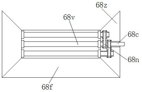
[0030] as attached Image 6 to the attached Figure 7 shown:
[0031] The filter plate mechanism 63 includes a support plate 63d, a top rod 63z, a positioning ball 63w, an outer frame 63b, a filter plate 63g, and a swing mechanism 63t. The support plate 63d is welded to the lower end of the filter box 65, and the support plate 63d The upper end is welded with the lower end of the ejector rod 63z, the upper end of the ejector rod 63z is provided with a positioning ball 63w, and the positioning ball 63w is installed at the inner middle end of the outer frame 63b by clearance fit, and the outer frame 63b is embedded with a filter plate 63g. The outer end of the outer frame 63b is installed inside the swing mechanism 63t, and the outer end of the swing mechanism 63t is fixedly installed inside the filter box 65. The filter plate 63g is located below the ejection mechanism 68f. It is symmetrically installed on both sides of the outer frame 63b, and the inner center of the outer frame 63b is positioned and oscillated around the positioning ball 63w, so that the two filter plates 63g inside the outer frame 63b swing and filter the water sample flowing downward.
[0032] The swing mechanism 63t includes a limit slot plate t5, a sliding shaft t8, a slide slot t1, and a spring t3. The outer end of the limit slot plate t5 is fixedly installed inside the filter box 65, and the outer end of the filter plate 63g is provided with Sliding shaft t8, the outer end of the filter plate 63g is slidably installed inside the limiting groove plate t5, the sliding shaft t8 is slidably installed inside the sliding groove t1, and a spring t3 is provided inside the sliding groove t1, and the spring t3 is connected with the sliding shaft t1. The shaft t8 is in conflict, the sliding groove t1 has an arc structure, and the arc center of the sliding groove t1 and the center of the positioning ball 63w are located at the same point, and there are two springs t3 inside the sliding groove t1, which are respectively connected with the sliding shaft. The upper and lower ends of t8 collide to ensure that the sliding shaft t8 drives the outer end of the outer frame 63b to perform a guided arc elastic swing inside the limiting groove plate t5, so that the outer frame 63b drives the filter plate 63g to swing repeatedly to eject the water sample for filtration. , to improve the filtering effect of the filter plate 63g on other impurities in the water sample, and at the same time prevent impurities from being blocked in the filter holes of the filter plate 63g.
[0033] The specific usage mode and function of this embodiment:
[0034] In the present invention, after the ferromagnetic impurities in the water sample are removed, the water sample continues to flow downward, and the outer frame 63b is pressed by the gravity of the water sample itself. At this time, the inner middle end of the outer frame 63b swings around the positioning ball 63w. When the two filter plates 63g inside the outer frame 63b swing to filter the water sample flowing downward, during the swinging process, the sliding shafts t8 at the left and right outer ends of the outer frame 63b perform arc-shaped guiding swings inside the sliding groove t1, The limiting groove plate t5 limits the swinging angle of the outer frame 63b, and the spring t3 inside the sliding groove t1 exerts repeated elastic force on the sliding shaft t8, so that the outer frame 63b repeatedly swings left and right around the center of the positioning ball 63w, Thereby, the two filter plates 63g inside the outer frame 63b are driven to perform ejection filtering on the water sample flowing downward, so as to improve the filtering effect of the filter plate 63g on other impurities in the water sample, and at the same time prevent impurities from clogging the filter of the filter plate 63g. in the hole.

PUM

no PUM

Description & Claims & Application Information

We can also present the details of the Description, Claims and Application information to help users get a comprehensive understanding of the technical details of the patent, such as background art, summary of invention, brief description of drawings, description of embodiments, and other original content. On the other hand, users can also determine the specific scope of protection of the technology through the list of claims; as well as understand the changes in the life cycle of the technology with the presentation of the patent timeline. Login to view more.

Similar technology patents

Through-flower heat dissipation device and method for handmade osmanthus tea

PendingCN111011555Aslow down the fallincrease contact time
Owner:和县赭洛山茶叶种植专业合作社

System for treating chloroaluminate ionic liquid spent catalyst and alkaline wastewater

ActiveCN109173956Aincrease contact timeCompletely hydrolyzed
Owner:CHINA UNIV OF PETROLEUM (BEIJING)

Classification and recommendation of technical efficacy words

  • Improve filtering effect
  • increase contact time

Gas filter device

InactiveCN102059031AImprove filtering effectImprove filtration capacity
Owner:赵艳萍

Air filter for engine

Owner:WUHU AOBENMA AUTOMOBILE PARTS

Medicine composite for treating vaginitis

Owner:SHENZHEN SOUTH CHINA PHARMA

Integrated ultra-clean desulfurization and dust collection device

ActiveCN105727700Aincrease contact timeHigh contact density
Owner:TONGZHENG ENVIRONMENT PROTECTION GRP CO LTD

Silicon removal method of low-grade bauxite

InactiveCN105197972Aincrease contact timeThe desilication reaction is sufficient
Owner:洛阳国兴矿业有限公司

Condensation type gas heating water heater

Owner:ZHEJIANG INOVISEN THERMAL ENERGY TECH CO LTD
Why Eureka
Try Eureka