Photocatalytic reactor

A photocatalytic reactor and catalyst-loaded technology, applied in the field of reactors, can solve the problems of matching and actual utilization gap, and achieve the effect of high effective irradiation intensity, high-efficiency catalytic effect, and volume reduction.

Pending Publication Date: 2022-08-05
曦赜生物科技(重庆)有限公司
View PDF0 Cites 0 Cited by
  • Summary
  • Abstract
  • Description
  • Claims
  • Application Information

AI Technical Summary

Problems solved by technology

However, with the increase in the number of lamp tubes, there is still a large gap between the matching with the catalyst and the actual utilization rate.

Method used


Image

  • Photocatalytic reactor
  • Photocatalytic reactor
  • Photocatalytic reactor

Examples


Embodiment 1

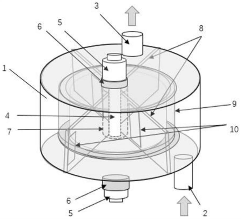
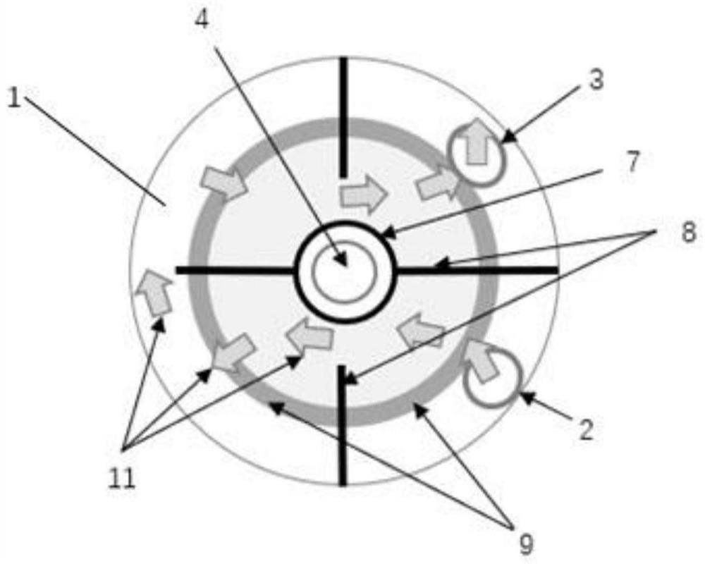
[0059] like figure 1 and figure 2 As shown, a photocatalytic reactor includes a shell, the shell is provided with a hollow cavity 1, a medium inlet 2 is provided on one side of the lower end of the shell, and a medium inlet 2 is provided on the side of the upper end of the shell There is a medium outlet 3;

[0060] The upper end and the lower end of the casing are respectively provided with a through hole for accommodating the lamp cap 5, and the lamp 4 passes through the through hole on the casing and is connected with the lamp holder, which is connected to the lamp holder. The casing is fixedly connected, a sealing ring 6 is arranged between the lamp cap 5 and the casing, and the light-emitting section of the lamp 4 is arranged in the cavity 1;

[0061] In the cavity 1, four partitions 8 are arranged along the axial direction of the lamp tube 4. The partitions 8 are provided with medium passage windows 10, and the adjacent medium passage windows 10 are arranged in a stagg...

Embodiment 2

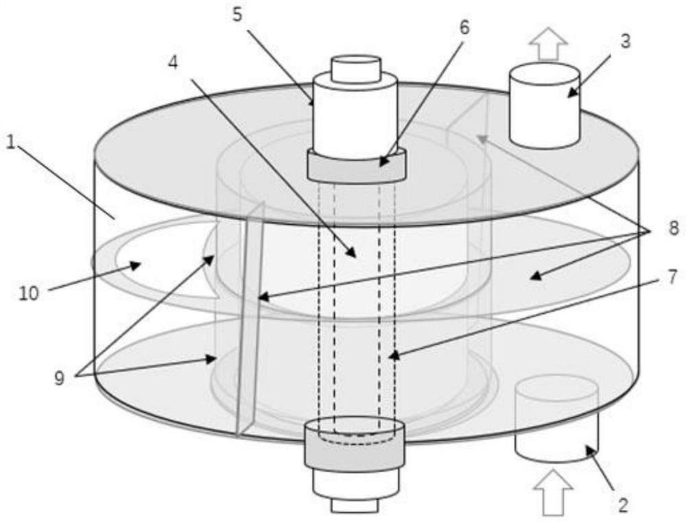
[0076] like image 3 and Figure 4 As shown in the figure, a photocatalytic reactor includes a shell, the shell is provided with a hollow cavity 1, a medium inlet 2 is provided on one side of the lower end of the shell, and one side of the lower end of the shell is provided with a medium inlet 2. There is a medium outlet 3;

[0077] The upper and lower ends of the casing are provided with a through hole for accommodating the lamp cap 5, and the lamp 4 passes through the through hole on the casing and is connected with the lamp holder, the lamp holder is connected to the lamp holder. The casing is fixedly connected, a sealing ring 6 is arranged between the lamp cap 5 and the casing, and the light-emitting section of the lamp 4 is arranged in the cavity 1;

[0078] A partition member 8 is arranged in the cavity 1 along the radial direction of the lamp tube 4, and a medium passage window 10 is arranged on the partition member 8. The medium inlet 2, the medium passage window 10,...

Embodiment 3

[0092] like Figure 5 and Image 6 As shown, Embodiment 3 is roughly the same as Embodiment 2, the only difference being:

[0093] 1. There are two medium inlets 2 on the lower side of the casing, and two medium outlets 3 on the upper side of the casing;

[0094] 2. In the cavity 1, a partition member 8 is provided along the axial direction and the radial direction of the lamp tube 4 respectively.


PUM


Abstract

The photocatalytic reactor comprises a shell, the shell is provided with a hollow cavity, one side of the upper end / lower end of the shell is provided with at least one medium inlet, and one side of the lower end / upper end of the shell is provided with at least one medium outlet; the upper end and / or the lower end of the shell are / is provided with at least one through hole for containing a lamp holder of the lamp tube, the lamp tube penetrates through the shell and is connected with the lamp tube fixing base, the lamp tube fixing base is fixedly connected with the shell, a sealing ring is arranged between the lamp holder of the lamp tube and the shell, and a light-emitting section of the lamp tube is arranged in the cavity. At least one separator is arranged in the cavity along the axial direction and / or the radial direction of the lamp tube, medium passing windows are arranged on the separators or medium passing windows are formed between the outer side walls of the separators and the inner side wall of the cavity, the adjacent medium passing windows are arranged in a staggered manner, and the medium inlet, the medium passing windows and the medium outlet which are communicated in sequence form a medium flowing channel. A catalyst-loaded carrier is arranged in at least part of the medium flow channel, and the catalyst-loaded carrier is arranged around the irradiation surface of the lamp tube.

Description

technical field [0001] The invention relates to a reactor, in particular to a photocatalytic reactor. Background technique [0002] With the acceleration of industrialization, the problem of environmental pollution has become more and more serious. The aggravation of air and water pollution caused by a large number of organic and inorganic by-products is having a profound impact on the ecosystem on which human beings depend, and is seriously threatening human health. Although there are many mature pollutant treatment technologies, exploring more efficient and lower-cost pollution treatment technologies has always been a research hotspot in the field of pollutant treatment. [0003] At present, the main pollutant treatment methods are: physical adsorption, chemical oxidation, microbial treatment and high temperature incineration. The above methods play an important role in environmental protection and governance. However, these technologies still have certain deficiencies ...

Claims


Application Information

Patent Timeline
Patent Type & Authority Applications(China)
IPC IPC(8): B01J19/12B01J8/02
CPCB01J19/12B01J8/02Y02W10/37
Inventor 陈长宏
Owner 曦赜生物科技(重庆)有限公司
Why Eureka
Try Eureka