Welding process and welding device of vacuum furnace

A welding device and welding process technology, applied in welding equipment, auxiliary devices, manufacturing tools, etc., can solve the problems of unstable welding quality, uneven heat distribution, low work efficiency, etc., and achieve enhanced welding effect, uniform heat distribution, even heating effect

Inactive Publication Date: 2022-08-05
韶山恒升机械工业有限公司
View PDF12 Cites 0 Cited by
  • Summary
  • Abstract
  • Description
  • Claims
  • Application Information

AI Technical Summary

Problems solved by technology

[0003] However, in the prior art, the heat is unevenly distributed inside the vacuum furnace body during the welding proce

Method used


Image

  • Welding process and welding device of vacuum furnace
  • Welding process and welding device of vacuum furnace
  • Welding process and welding device of vacuum furnace

Examples


Embodiment 1

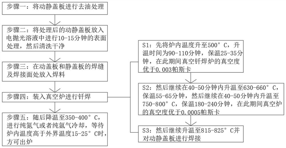
[0037] see figure 1 As shown, the present invention is a welding process of a vacuum furnace, comprising:

[0038] Step 1: Degrease the static and dynamic cover plate;

[0039] Step 2: Put the treated dynamic and static cover plate into the electropolishing solution for 10-15 minutes of surface treatment, and then clean it;

[0040] Wherein, the raw material weight ratio of the electropolishing solution is: sulfuric acid 25-35 phosphoric acid 15-25 water 45-55;

[0041] Step 3: Put solder on the welding seam and welding surface of the moving cover plate and the static cover plate;

[0042] Step 4: Load into a vacuum furnace for brazing;

[0043] Wherein, the heating steps inside the vacuum furnace are as follows:

[0044] S1: first raise the temperature in the furnace to 500°C, the heating time is 90-110 minutes, and the temperature is kept for 25-35 minutes, during which the vacuum degree of the vacuum brazing furnace is better than 0.003 Pascal;

[0045] S2: then continue...

Embodiment 2

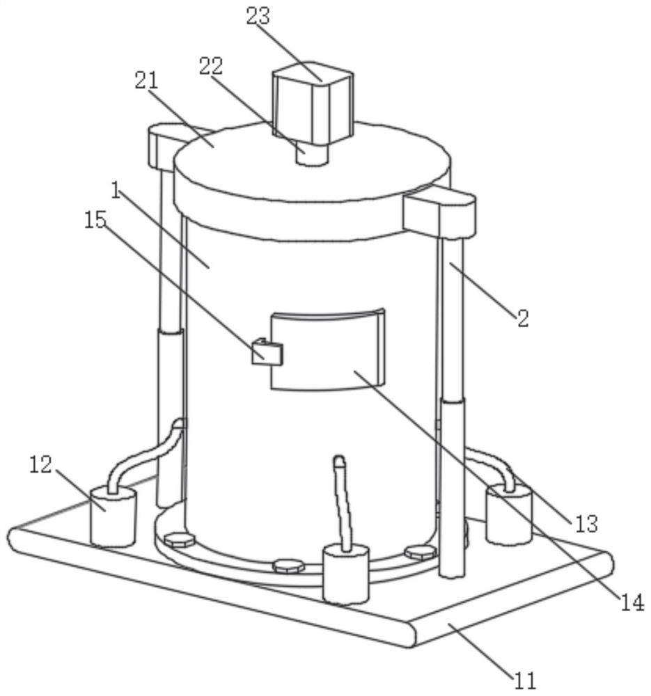
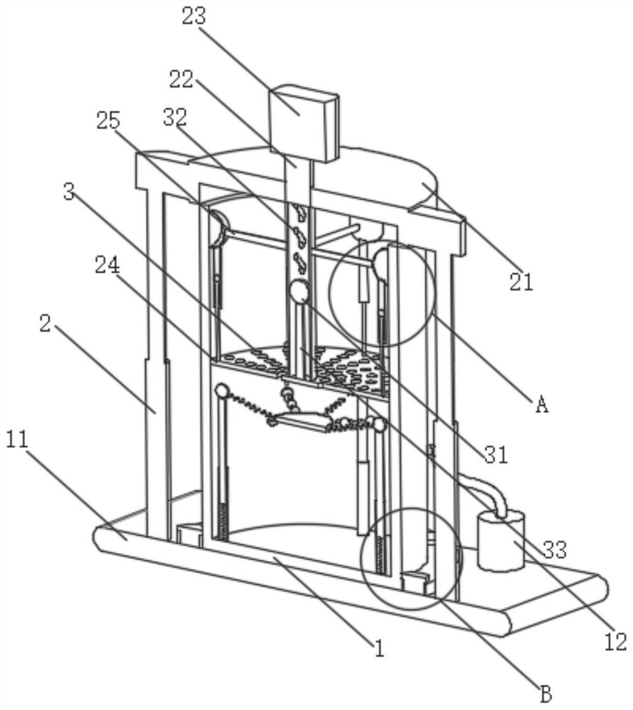
[0049] see Figure 2-Figure 7 As shown, the present invention is a welding device of a vacuum furnace, including a furnace body 1, the purpose of this setting is to facilitate welding, and the bottom of the furnace body 1 is fixedly connected with a bottom plate 11, and the purpose of this setting is to facilitate the welding of the furnace body 1. For support, the top opening of the furnace body 1 is set, and the purpose of this setting is to facilitate the limiting of the furnace body 1. The four sides of the bottom plate 11 are respectively fixed and connected with a suction cylinder 12. The purpose of this setting is to facilitate the suction, the suction cylinder The top of 12 is communicated with a suction hose 13. The purpose of this setting is to facilitate the transportation of gas. The end of the suction hose 13 away from the suction cylinder 12 is communicated with the lower side wall of the furnace body 1. The purpose of this setting is In order to facilitate the f...


PUM


Abstract

The invention discloses a welding process and a welding device for a vacuum furnace. The welding process comprises the following steps: step 1, deoiling a movable cover plate and a static cover plate; secondly, the treated movable and static cover plates are put into an electropolishing solution to be subjected to surface treatment for 10-15 minutes, and then the movable and static cover plates are cleaned up. When a worker places the treated movable and static cover plates on a placing plate in the furnace body, a motor is started to enable the placing plate to rotate under the action of a rotating shaft; meanwhile, a heating pipe and an air suction cylinder are started, the interior of the furnace body can be in a vacuum state through starting of the air suction cylinder, high temperature can be generated in the furnace body through starting of the heating pipe, and therefore the purpose of welding the welding flux between the movable cover plate and the static cover plate is achieved; in this state, compared with a traditional static state, the movable cover plate and the static cover plate can be heated evenly, and therefore the welding effect of the device can be enhanced.

Description

technical field [0001] The invention relates to the technical field of vacuum furnace welding, in particular to a welding process and a welding device of a vacuum furnace. Background technique [0002] When electronic components such as diodes, triodes, thyristors or bridges are produced, chips need to be welded between the upper and lower wafers. This process is called bonding. The specific working process of the lamination is as follows: first, you need to apply solder paste on the upper side of the lower material, and place the chip in the specific position of the lower material, and then stack the upper material with solder paste on the lower side on the lower material. On the upper side of the chip, the top cover of the welding mold is closed on the bottom plate of the welding mold, and finally the welding mold is sent into the welding furnace for welding. The welding of the blanks needs to be carried out in a vacuum furnace. [0003] However, in the prior art, heat i...

Claims


Application Information

Patent Timeline
IPC IPC(8): B23K1/00B23K1/20B23K3/00B23K3/08
CPCB23K1/00B23K1/20B23K3/00B23K3/085B23K3/08
Inventor 李会媛
Owner 韶山恒升机械工业有限公司
Why Eureka
Try Eureka