Auxiliary clamping device for plane milling machine
A technology of auxiliary clamping and plane milling machine, applied in the field of milling machines, can solve the problem that the use performance of the clamping device cannot meet the needs of use, and achieve the effect of ensuring stability and continuity, and improving speed and efficiency.
- Summary
- Abstract
- Description
- Claims
- Application Information
AI Technical Summary
Problems solved by technology
Method used
Image
Examples
Embodiment 1
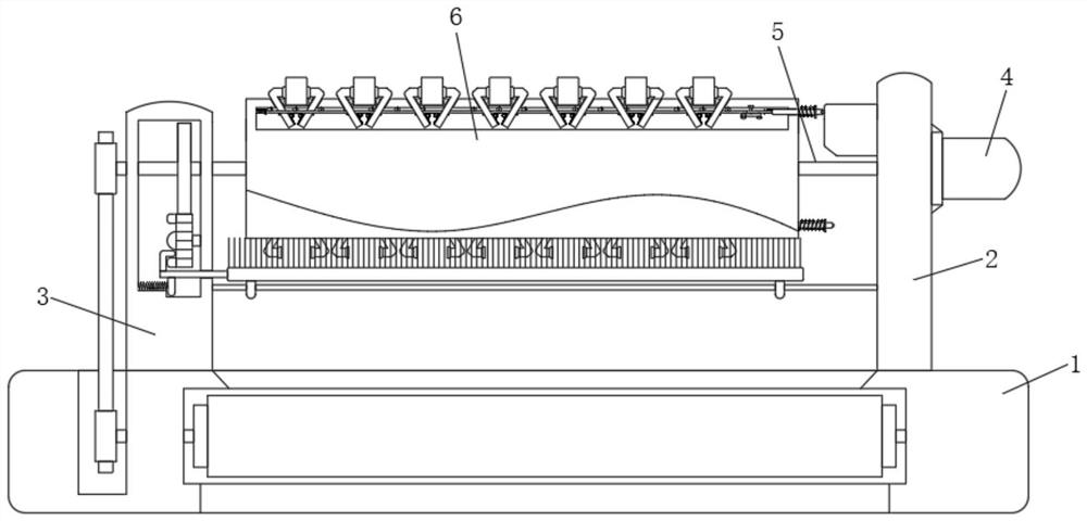
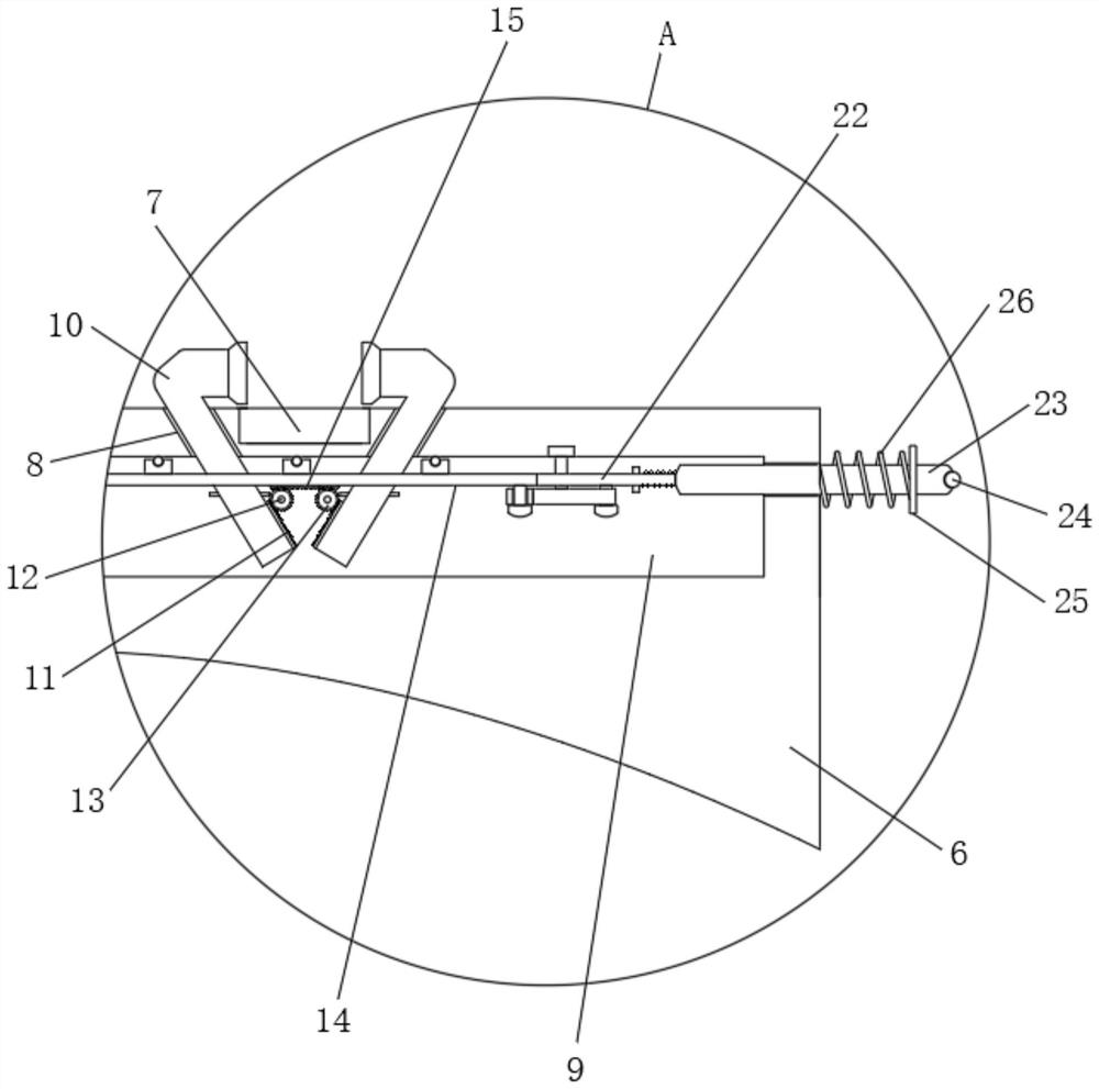
[0032] Example one, by Figure 1 to Figure 10 Given, the present invention includes a workbench 1, the workbench 1 is installed on the milling machine, the two ends of the top of the workbench 1 are respectively fixed with a vertical block 2 and a vertical block 3, and a motor 4 is installed on one side of the vertical block 2. , the opposite sides of vertical block one 2 and vertical block two 3 are rotatably installed with rotating shaft 5, one end of one rotating shaft 5 is connected with the output end of motor 4, and a square bar rotating table is fixedly installed between the two rotating shafts 5 6. The four sides of the square bar turntable 6 are provided with workpiece placement grooves 7 at equal distances, the two sides of the workpiece placement groove 7 are symmetrically provided with inclined grooves 8, and the inside of the four sides of the square bar turntable 6 are provided with transmission chambers 9, and inclined grooves 8. A "7"-shaped clamping block 10 i...
Embodiment 2
[0041] In the second embodiment, on the basis of the first embodiment, one end of the rotating shaft 5 on the second vertical block 3 extends to one side of the second vertical block 3 and is fixedly installed with the first sprocket 32. The top of the workbench 1 is provided with a collection device. Slot 33, rollers 34 are installed at both ends of the collecting slot 33, and a conveyor belt 35 is installed between the surfaces of the two rollers 34. The top of the table 1 is provided with a groove 36, and one end of one of the rollers 34 extends to the recess. A second sprocket 37 is installed inside the groove 36, and a chain 38 is installed between the second sprocket 37 and the first sprocket 32, so as to effectively collect and transmit the processed workpieces;
[0042] After the workpiece is milled, start the motor 4 to rotate forty-five degrees to mount the workpiece again, and then rotate the motor 4 for another forty-five degrees to clamp the mounted workpiece; at t...
Embodiment 3
[0044] Embodiment 3, on the basis of Embodiment 1, a cavity 39 is opened in the middle of the vertical block 3, one of the rotating shafts 5 penetrates through the cavity 39, and one of the rotating shafts 5 is located inside the cavity 39. The surface is fixedly installed with a cavity 39. In the large gear 40, a pinion 41 is rotated and installed on one side inside the cavity 39. The pinion 41 is meshed and connected with the large gear 40, and a sector block 42 is fixedly installed on one side of the pinion 41 at an equal distance; the lower part of the cavity 39 runs through A plunger 43 is installed, one end of the plunger 43 is installed with an inverted L-shaped extrusion block 44, the upper part of the inverted L-shaped extrusion block 44 is in contact with the sector block 42, and the bottom of the plunger 43 is installed with a fixed piece 45, the fixed piece A spring three 46 is connected between 45 and the lower part of the cavity 39, so that the transmission can be...
PUM
 Abstract
Description
Claims
Application Information
 - R&D
- Intellectual Property
- Life Sciences
- Materials
- Tech Scout
- Unparalleled Data Quality
- Higher Quality Content
- 60% Fewer Hallucinations
Browse by: Latest US Patents, China's latest patents, Technical Efficacy Thesaurus, Application Domain, Technology Topic, Popular Technical Reports.
© 2025 PatSnap. All rights reserved.Legal|Privacy policy|Modern Slavery Act Transparency Statement|Sitemap|About US| Contact US: help@patsnap.com


