Supercharge Your Innovation With Domain-Expert AI Agents!

Protective metal plate structure of numerical control machine tool

A CNC machine tool and sheet metal technology, which is applied in metal processing equipment, maintenance and safety accessories, metal processing machinery parts, etc., can solve the problems affecting the repeated positioning accuracy of machine tools, cracking and deformation, and high operating noise, and achieves simple structure, Long service life and good protection performance

Inactive Publication Date: 2022-08-05
南京京驰数控装备有限公司
View PDF0 Cites 0 Cited by
  • Summary
  • Abstract
  • Description
  • Claims
  • Application Information

AI Technical Summary

Problems solved by technology

[0003] At present, steel telescopic protective covers are widely used in this field, which play an effective role in preventing the entry of chips and other liquids, and have become the standard configuration in the industry. However, with the increase in processing efficiency requirements It is getting higher and higher, especially the fast moving speed of small drilling and tapping CNC machine tools is getting faster and faster, from 48 meters per minute to 60 meters per minute, and to linear motors of 80 meters per minute or more. Standard configuration, at such a high fast-moving speed, the disadvantages and short boards of the steel telescopic protective cover are becoming more and more prominent, because the telescopic protective cover moves synchronously with the workbench, it is easy to be cracked and deformed, and the operation noise large, which seriously affects the repetitive positioning accuracy of the machine tool's rapid movement, so a shield structure design that adapts to high-speed machining efficiency and can match the high-speed machining of small CNC machine tools becomes extremely important. In order to solve the above problems, a CNC machine tool The protective sheet metal structure needs to be developed urgently

Method used


Image

  • Protective metal plate structure of numerical control machine tool
  • Protective metal plate structure of numerical control machine tool
  • Protective metal plate structure of numerical control machine tool

Examples


Embodiment Construction

[0023] The technical solutions in the embodiments of the present invention will be clearly and completely described below with reference to the accompanying drawings in the embodiments of the present invention. Obviously, the described embodiments are only a part of the embodiments of the present invention, but not all of the embodiments. Based on the embodiments of the present invention, all other embodiments obtained by those of ordinary skill in the art without creative efforts shall fall within the protection scope of the present invention.

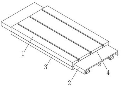
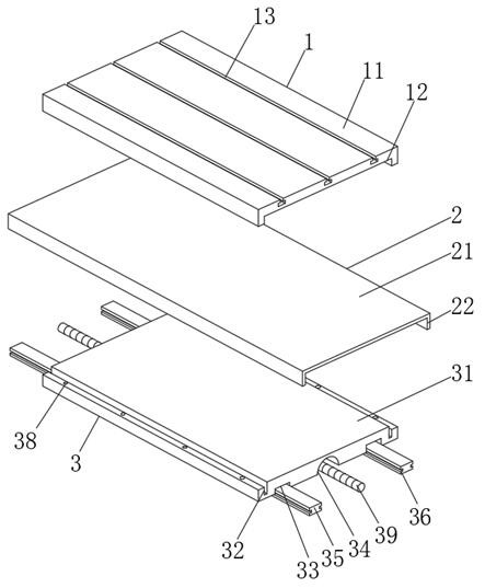
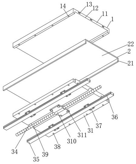
[0024] see Figure 1-4 , the present invention provides a technical solution: a protective sheet metal structure of a CNC machine tool, comprising:

[0025] The upper worktable structure 1 includes an upper worktable casting 11, a lower groove 12 is formed at the bottom of the surface of the upper worktable casting 11, and a number of T-shaped equidistant distributions are formed on the surface of the upper worktable casting 11 The g...


PUM


Abstract

The protective metal plate structure of the numerical control machine tool comprises an upper workbench structure, the upper workbench structure comprises an upper workbench casting, a lower groove is formed in the bottom of the surface of the upper workbench casting, and a plurality of T-shaped grooves distributed at equal intervals are formed in the surface of the upper workbench casting; a plurality of upper connecting threaded holes distributed at equal intervals are formed in the two sides of the bottom of the upper workbench casting. The protective metal plate structure can axially move at an ultra-high speed while protecting a lead screw guide rail of a machine tool, the service life of the protective metal plate and the influence on the machining precision of the machine tool do not need to be considered at all, and the protective metal plate structure is a lifelong maintenance-free protective cover under the normal use condition; the protective metal plate structure of the numerical control machine tool has the advantage of being good in protective performance, is simple in structure, easy to achieve and long in service life in the actual using process, and has wide application prospects.

Description

technical field [0001] The invention relates to the technical field of numerical control machine tools, in particular to a protective sheet metal structure of a numerical control machine tool. Background technique [0002] In the field of CNC machine tools, most of the transmission and accuracy of axial movement are realized by servo motors through linear guide rails and ball screws of transmission parts, so the protection of linear guides and screw rods is very important, and it will be directly Affect the machining accuracy and service life of CNC machine tools. [0003] At present, the steel telescopic protective cover is widely used in this field, which plays an effective protective role in preventing the entry of chips and other liquids, and has become the standard configuration in the industry. However, with the increase in processing efficiency requirements It is getting higher and higher, especially the fast moving speed of small drilling and tapping CNC machine too...

Claims


Application Information

Patent Timeline
IPC IPC(8): B23Q11/08B23Q11/00
CPCB23Q11/0825B23Q11/00Y02P70/10
Inventor 张诚
Owner 南京京驰数控装备有限公司
Features
  • R&D
  • Intellectual Property
  • Life Sciences
  • Materials
  • Tech Scout
  • Unparalleled Data Quality
  • Higher Quality Content
  • 60% Fewer Hallucinations
Learn More