
Automobile brake drum machining positioning structure and machining device thereof

A technology for automobile braking and processing devices, which is applied in the direction of grinding workpiece supports, etc., can solve the problems of inconvenient fixing and slow grinding efficiency, and achieve the effect of improving grinding efficiency and simple and quick positioning method.

Active Publication Date: 2022-08-05
HEFEI JAC CASTING
View PDF12 Cites 0 Cited by
  • Summary
  • Abstract
  • Description
  • Claims
  • Application Information

AI Technical Summary

Problems solved by technology

[0002] The brake drum is a part of the drum brake system. When braking, the piston exerts pressure on the two pairs of half-moon brake shoes to make them stick to the inner wall of the drum, thereby generating friction to stop the rotation of the wheel. The brake drum is in the shape of a basin , the inside of the brake drum is usually provided with through grooves and assembly holes. Before the brake drum leaves the factory, the through grooves and assembly holes need to be polished separately. The efficiency of grinding alone is relatively slow. It is inconvenient to use a fixture to fix the brake drum during processing, so a processing positioning structure and a processing device for an automobile brake drum are needed

Method used


Image

  • Automobile brake drum machining positioning structure and machining device thereof
  • Automobile brake drum machining positioning structure and machining device thereof
  • Automobile brake drum machining positioning structure and machining device thereof

Examples


Embodiment 1

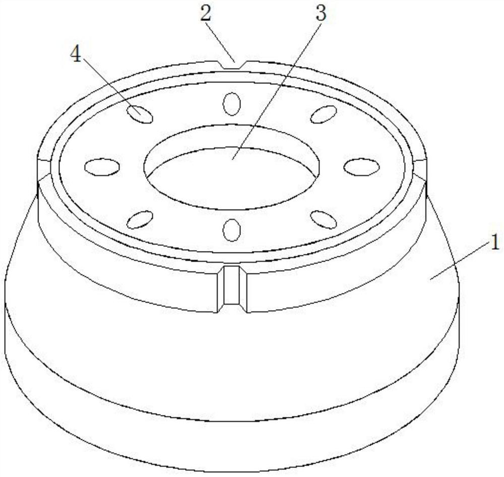
[0028] Example 1, refer to figure 1 , an automobile brake drum processing and positioning structure, including a drum body 1, an assembly hole 4 and a through groove 3 opened inside the drum body 1, and characterized in that it includes a positioning groove 2 opened on the outer ring of the drum body 1.

Embodiment 2

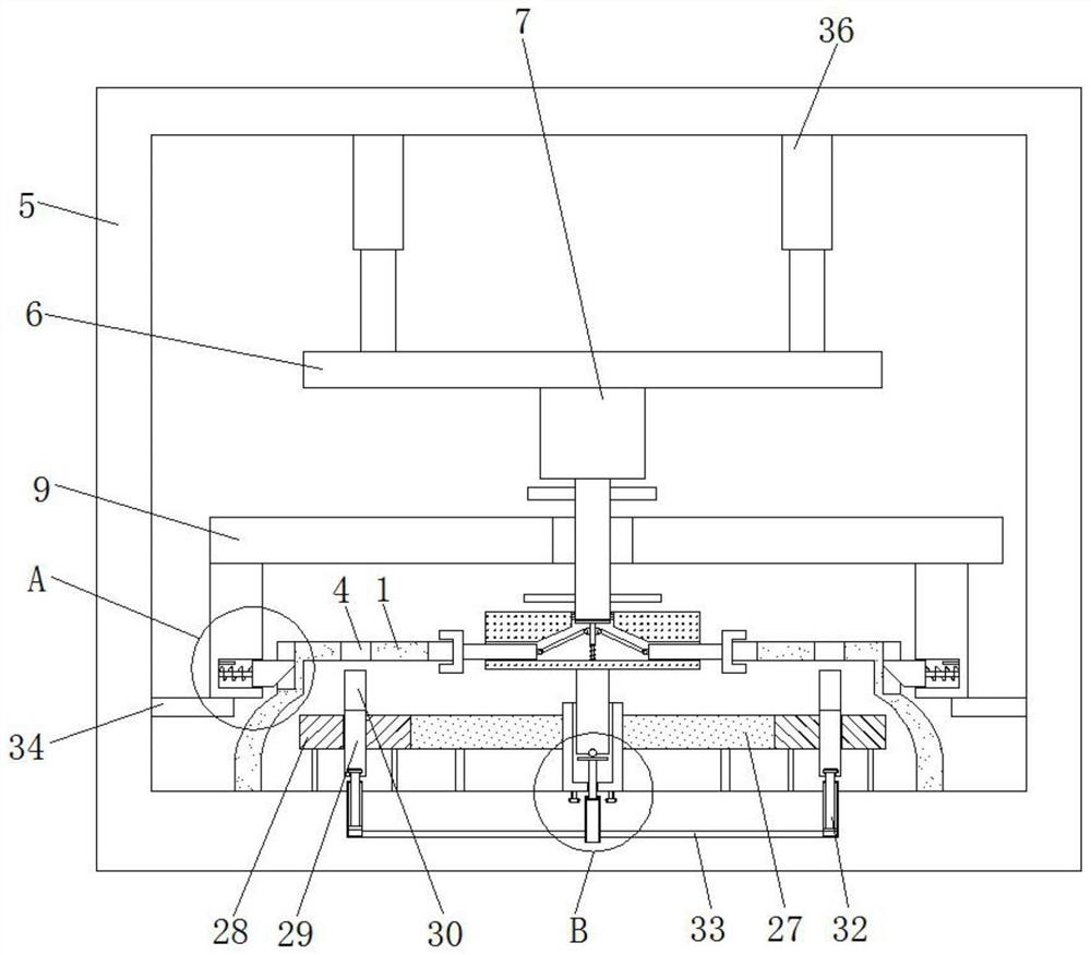
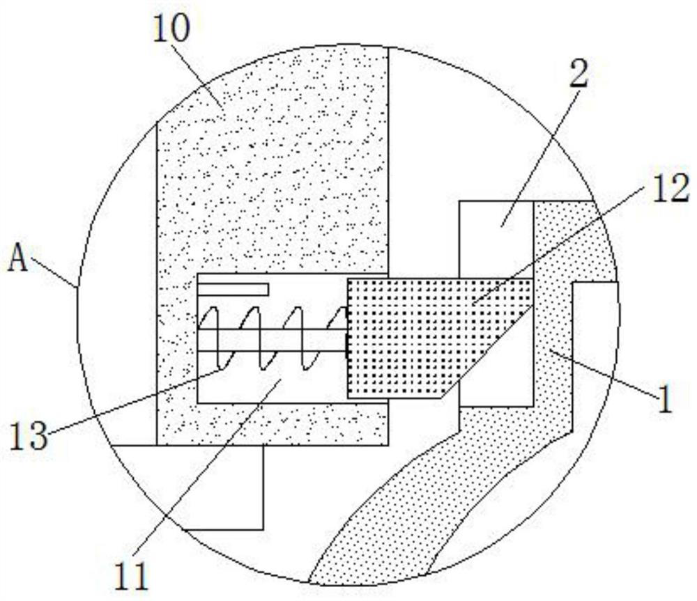
[0029] Example 2, refer to Figure 2-7 , an automobile brake drum processing device, comprising a housing 5 and a positioning mechanism for fixing the drum body 1, the positioning mechanism comprises a first fixed plate 9 that is slidably sleeved on the outside of the drive shaft 8, the bottom end of the first fixed plate 9 And the position relative to the positioning groove 2 is fixed with a second fixing plate 10 , a first installation groove 11 is opened inside the second fixing plate 10 , and the interior of the first installation groove 11 is horizontally slidably inserted with the matching positioning groove 2 to be snapped. The used clamping block 12, and a horizontally arranged first spring 13 is fixed between the first installation groove 11 and the clamping block 12, the inner bottom wall of the outer casing 5 is provided with a fixing groove for use with the drum body 1, and the inner bottom wall of the outer casing 5 is provided. The top wall is connected with a fi...


PUM


Abstract

The invention belongs to the technical field of automobile parts and machining, particularly relates to an automobile brake drum machining positioning structure and a machining device thereof, and provides the following scheme that the automobile brake drum machining positioning structure comprises a drum body, an assembly hole and a through groove which are formed in the drum body, and a positioning groove formed in the outer ring of the drum body. The machining device for the automobile brake drum comprises a shell and a positioning mechanism used for fixing a drum body, a fixing groove used in cooperation with the drum body is formed in the inner bottom wall of the shell, and a first mounting plate is connected to the inner top wall of the shell through an electric telescopic rod. The positioning grooves are formed in the drum body, so that the drum body can be conveniently fixed by a clamp to be machined; the driving shaft arranged in the machining device and connected with the driving motor drives the first grinding head to rotate, so that the inner wall of the through groove in the drum body is ground, meanwhile, the driving shaft can drive the second grinding head to synchronously grind the inner walls of the multiple assembly holes, and the grinding efficiency is improved.

Description

technical field [0001] The invention relates to the technical field of automobile parts and processing, in particular to a processing and positioning structure of an automobile brake drum and a processing device thereof. Background technique [0002] The brake drum is a part of the drum brake system. When braking, the piston exerts pressure on the two pairs of half-moon brake shoes to make them close to the inner wall of the drum, thereby generating friction to stop the rotation of the wheel. The brake drum is in the shape of a basin. , The interior of the brake drum is usually provided with through grooves and assembly holes. Before the brake drum leaves the factory, the through grooves and assembly holes need to be polished separately, and the grinding efficiency is slow. It is inconvenient to use a fixture to fix the brake drum during processing, so a processing and positioning structure of an automobile brake drum and a processing device thereof are required. SUMMARY O...

Claims


Application Information

Patent Timeline
Patent Type & Authority Applications(China)
IPC IPC(8): B24B41/06
CPCB24B41/06
Inventor 张莹朱传玲岑军张安文
Owner HEFEI JAC CASTING
Learn More