
Shadow ring and reaction cavity structure comprising same

A technology of reaction chamber and shadow, which is applied in metal material coating process, coating, gaseous chemical plating, etc., can solve the problems of poor uniformity, ignoring the concentricity of wafer and edge ring, and the difference in edge morphology of deposited films. Achieve the effect of improving uniformity and avoiding long film on the edge and back

Active Publication Date: 2022-08-05
PIOTECH CO LTD
View PDF5 Cites 2 Cited by
  • Summary
  • Abstract
  • Description
  • Claims
  • Application Information

AI Technical Summary

Problems solved by technology

[0002] In the prior art, when depositing thin films on the wafer, the edge ring is used to prevent the edge of the film from growing. The fixing method is to use three positioning pins to fix the edge ring on the substrate holder, although the concentricity between the edge ring and the heating plate is ensured. However, due to the offset of the film transfer and the offset of the wafer caused by ventilation, the concentricity between the wafer and the edge ring is ignored, which leads to differences in the morphology of the edge of the deposited film and poor uniformity. question

Method used


Image

  • Shadow ring and reaction cavity structure comprising same
  • Shadow ring and reaction cavity structure comprising same
  • Shadow ring and reaction cavity structure comprising same

Examples


Embodiment Construction

[0027] The technical solutions of the present invention will be clearly and completely described below with reference to the embodiments. Obviously, the described embodiments are part of the embodiments of the present invention, but not all of the embodiments. Based on the embodiments of the present invention, all other embodiments obtained by those of ordinary skill in the art without creative efforts shall fall within the protection scope of the present invention.

[0028] It will be understood by those skilled in the art that, unless otherwise defined, all terms (including technical and scientific terms) used herein have the same meaning as commonly understood by one of ordinary skill in the art to which this invention belongs. It should also be understood that terms, such as those defined in a general dictionary, should be understood to have meanings consistent with their meanings in the context of the prior art and, unless specifically defined as herein, should not be inte...


PUM


Abstract

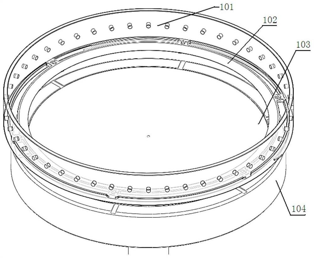
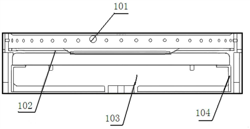
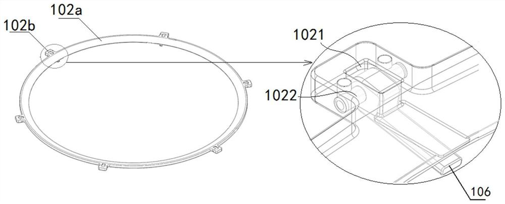
The invention provides a shadow ring and a reaction chamber structure, the shadow ring comprises a ring body, a plurality of projections and a plurality of plectrum structures, the ring body comprises an annular inner wall and an annular outer wall; the plurality of protruding parts are arranged at intervals in the circumferential direction of the annular outer wall and are used for being matched with an air exhaust ring in the reaction cavity structure; the shifting piece structures correspond to the protruding parts one to one, one ends of the shifting piece structures are rotationally connected with the protruding parts, the other ends of the shifting piece structures extend to the position below the ring body, and therefore an opening and closing angle is formed between the shifting piece structures and the lower surface of the ring body. As the rotatable guide plectrum is arranged below the ring body of the shadow ring, the guide plectrum structure rotates in the ascending process of the ceramic sleeve, and the opening angle between the guide plectrum structure and the lower surface of the ring body is gradually reduced, the position of a wafer is adjusted, the problem of wafer deviation caused by wafer conveying and ventilation is solved, films on the edge and the back surface of the wafer are prevented from growing, and the wafer quality is improved. And the film morphology at the edge of the surface of the wafer and the uniformity of the film in the wafer are improved.

Description

technical field [0001] The present invention relates to the technical field of semiconductor wafer processing equipment, and in particular, to a shadow ring and a reaction chamber structure including the shadow ring. Background technique [0002] In the prior art, when the wafer is deposited, the edge ring is used to prevent the edge from growing. The fixing method is to use three positioning pins to fix the edge ring on the substrate frame, although the concentricity of the edge ring and the heating plate is ensured. However, due to the offset of the film transfer and the offset of the wafer caused by ventilation, the concentricity of the wafer and the edge ring is ignored, resulting in differences in the morphology of the edge of the deposited film, and poor uniformity. question. [0003] Therefore, how to control the film morphology and uniformity at the edge of the wafer surface during the film deposition process is an urgent problem to be solved. SUMMARY OF THE INVEN...

Claims


Application Information

Patent Timeline
Patent Type & Authority Applications(China)
IPC IPC(8): C23C16/458C23C16/50C23C16/52
CPCC23C16/50C23C16/52C23C16/4585Y02P70/50
Inventor 周伟杰柴智
Owner PIOTECH CO LTD
Learn More