Multi-path dynamic water seepage erosion simulation test device considering disturbance and initial state
A technology of simulating test and initial state, applied in the field of geotechnical engineering, can solve the problems of ignoring the common coupling effect, raising the water head, and inconvenient test, so as to simplify the test operation and improve the test efficiency
- Summary
- Abstract
- Description
- Claims
- Application Information
AI Technical Summary
Problems solved by technology
Method used
Image
Examples
Embodiment 1
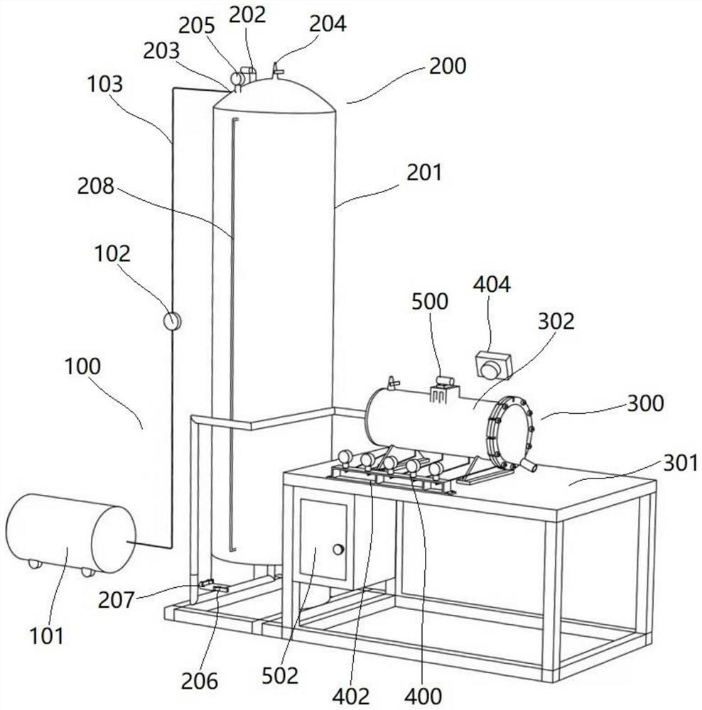
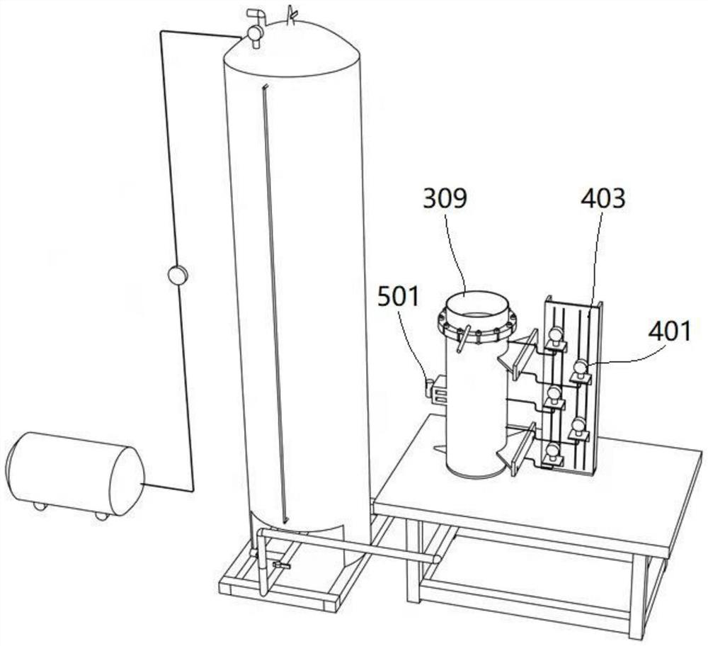
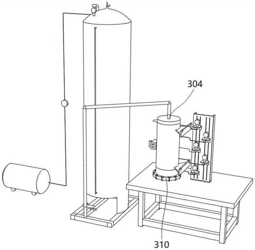
[0032] like Figure 1-Figure 4 As shown, Embodiment 1 of the present invention provides a multi-path dynamic water seepage erosion simulation test device considering disturbance and initial state, including a constant pressure component 100, a water supply component 200, a coarse-grained soil seepage component 300, and a data acquisition component 400 .
[0033] The coarse-grained soil seepage assembly 300 includes a test bed 301 and a test cylinder 302 installed on the test bed 301. The test cylinder 302 can be arranged horizontally or vertically to simulate a horizontal seepage path and a vertical seepage path, respectively. Specifically, when the test cylinder 302 is arranged horizontally, the test cylinder 302 is placed on the test table 301 through the support; and when the test cylinder 302 is arranged vertically, a stepped mounting hole is opened on the test table 301, so that the test cylinder 302 It can be erected on the test stand 301 smoothly, and the bottom end is...
specific Embodiment approach
[0052] Embodiment 2 of the present invention provides a specific implementation of a horizontal seepage path, including the following steps:
[0053] Step 1: Load the coarse-grained soil sample into the test column 303 .
[0054] Step 2: Connect each part of the device: connect the air pump 101 to the water supply tank through the air pipe 103, the water outlet 206 of the water supply tank is connected to the first water inlet 304 of the test tube 302, and the pressure measuring hole 311 and the digital display pressure gauge 401 are tested. Press the pipe connection, put the screen of the test cylinder into the connection between the flange 307 and the horizontal seepage joint 308, connect the horizontal seepage joint 308 and the test column 303, place the test cylinder 302 on the test bench 301 horizontally, and fix the test with bolts The support of the cylinder 302, the horizontal pressure gauge fixing plate 402 is installed on the test bench 301, and the dual-view detecti...
Embodiment 3
[0060] Embodiment 3 of the present invention provides a specific implementation of a vertical seepage path (bottom-up or top-down), including the following steps:
[0061] Step 1: Load the coarse-grained soil sample into the test column 303 .
[0062] Step 2. Connect each part of the device: connect the air pump 101 to the water supply tank through the air pipe 103, the water outlet 206 of the water supply tank is connected to the first water inlet 304 of the test tube 302, and the pressure measuring hole 311 and the digital display pressure gauge 401 are tested. Press the pipe connection, put the test cylinder screen into the connection between the flange 307 and the first vertical seepage joint 309 (or the second vertical seepage joint 310), and connect the first vertical seepage joint 309 (or the second vertical seepage joint 309). The seepage joint 310) and the test column 303, the test cylinder 302 is placed upright on the test bench 301, the vertical pressure gauge fixin...
PUM
 Abstract
Description
Claims
Application Information
 - R&D
- Intellectual Property
- Life Sciences
- Materials
- Tech Scout
- Unparalleled Data Quality
- Higher Quality Content
- 60% Fewer Hallucinations
Browse by: Latest US Patents, China's latest patents, Technical Efficacy Thesaurus, Application Domain, Technology Topic, Popular Technical Reports.
© 2025 PatSnap. All rights reserved.Legal|Privacy policy|Modern Slavery Act Transparency Statement|Sitemap|About US| Contact US: help@patsnap.com


