Automobile sealing strip machining equipment and method

A technology for automobile sealing strips and processing equipment, which is applied to household appliances, household components, other household appliances, etc., can solve the problems of increasing production site pressure, backward production technology, waste of heat energy, etc., and achieves reduction of failure rate, less water consumption, The effect of improving heat dissipation efficiency

Pending Publication Date: 2022-08-09
GUANGZHOU XINQIANG AUTOMOTIVE COMPONENTS CO LTD
View PDF0 Cites 0 Cited by
  • Summary
  • Abstract
  • Description
  • Claims
  • Application Information

AI Technical Summary

Problems solved by technology

[0003] In the production and processing process of the above-mentioned automobile sealing strips, the extrusion process and the vulcanization process cannot be manually operated, and the equipment is fully automated for production and processing. However, in the cooling process at the back end of the production of automobile sealing strips, there are still a large number of cheap water tanks on the market The production process is very backward, but due to the high cost of purchasing and using special cooling equipment, simple water tank cooling is still largely reserved , this type of cooling process has obvious disadvantages: First, the vulcanization equipment for automobile sealing strips is generally tunnel-type, and the length generally fluctuates between 20 meters and 40 meters, which already has high requirements for the production site. The cooling water tank and packing workbench will further increase the pressure of the production site. Second, the surface of the automobile sealing strip cooled by the cooling water tank contains a lot of water. Drying treatment, thirdly, the temperature of the automobile sealing strip just out of the vulcanization tunnel is very high, and the heat energy is completely wasted after cooling in the simple water tank

Method used


Image

  • Automobile sealing strip machining equipment and method
  • Automobile sealing strip machining equipment and method
  • Automobile sealing strip machining equipment and method

Examples


Embodiment Construction

[0036] The technical solutions of the present invention will be clearly and completely described below with reference to the accompanying drawings. In the description of the present invention, it should be noted that the terms "center", "upper", "lower", "left", "right", "vertical", "horizontal", "inner", "outer", etc. The indicated orientation or positional relationship is based on the orientation or positional relationship shown in the accompanying drawings, which is only for the convenience of describing the present invention and simplifying the description, rather than indicating or implying that the indicated device or element must have a specific orientation or a specific orientation. construction and operation, and therefore should not be construed as limiting the invention. Furthermore, the terms "first", "second", and "third" are used for descriptive purposes only and should not be construed to indicate or imply relative importance.

[0037]In the description of the ...


PUM


Abstract

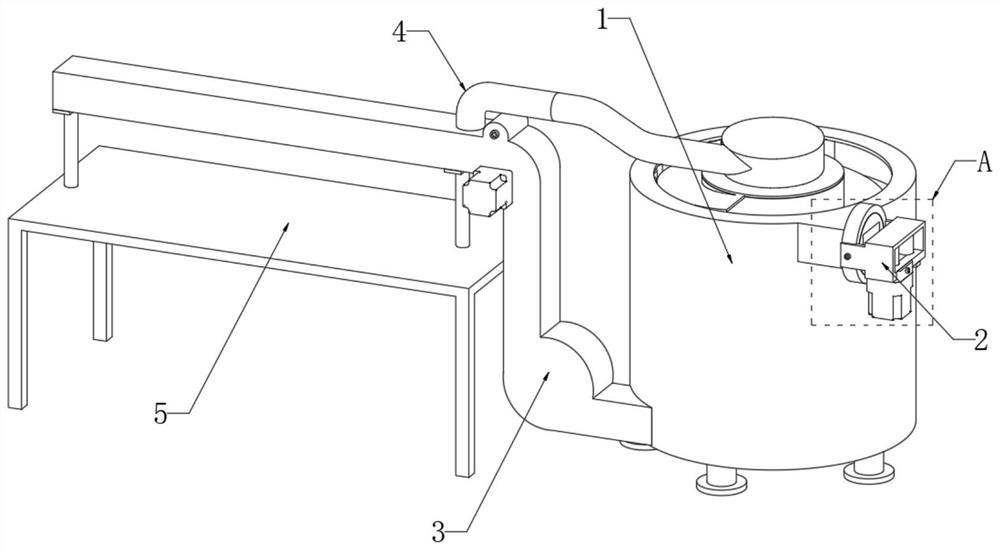
The invention discloses automobile sealing strip processing equipment and method, relates to the field of automobile sealing strips, and provides the following scheme aiming at the problems of large occupied area and low cooling efficiency of the existing automobile sealing strip cooling equipment: the automobile sealing strip processing equipment comprises a cooling mechanism for cooling a sealing strip and a drying mechanism for drying the sealing strip, the cooling mechanism comprises an outer tank and an inner tank, the inner tank is sleeved with the outer tank, clear water used for cooling the sealing strip is contained between the inner tank and the outer tank, and a spiral sliding plate used for supporting the sealing strip in a sliding mode is spirally arranged on the outer wall of the inner tank. A first rolling shaft and a second rolling shaft which are used for guiding sliding of the sealing strip and reducing friction force are arranged on the inner wall of the outer tank, and the sealing strip penetrates through the cooling mechanism along a spiral path to be cooled. The device is novel and compact in structure, low in use and maintenance cost, capable of running semi-automatically or automatically, capable of replacing existing manual and backward cooling process equipment and worthy of popularization.

Description

technical field [0001] The invention relates to the field of automobile weather strips, and in particular, to equipment and methods for processing automobile weather strips. Background technique [0002] Car weather strips are generally found between the car door frame and the door opening of the car body. They are used to seal the gap between the car door and the car body after the door is closed. The car weather strips are usually made of rubber. The production of car weather strips requires the raw materials of rubber particles to be put into first. In the extruder, the heated rubber granules are softened and fused, and then extruded from the molding die through the screw structure to obtain a strip-shaped rubber strip with a specific cross-sectional profile. At this time, the rubber strip is only formed, and needs to be High-temperature vulcanization is carried out through a vulcanization equipment line with a length of tens of meters, and the vulcanized rubber strip can...

Claims


Application Information

Patent Timeline
Patent Type & Authority Applications(China)
IPC IPC(8): B29C35/16B29C37/00B29L31/26
CPCB29C35/16B29C37/0092B29C2035/1616B29L2031/265
Inventor 詹绍谈吕秋霞罗志雄杨师丛戴爱平谭焕燕孙乐龚志业李艳琼
Owner GUANGZHOU XINQIANG AUTOMOTIVE COMPONENTS CO LTD
Why Eureka
Try Eureka