Oil pumping unit protection device special for oil production engineering and using method of oil pumping unit protection device

A protection device and pumping unit technology, which is applied in the direction of mining fluid, earthwork drilling, wellbore/well components, etc., can solve the problems of unstable well pressure, increased wear of parts, stuck pumps, etc., and reduce sand content , prolong the service life, increase the effect of parts wear

Inactive Publication Date: 2022-08-09
张谦
View PDF0 Cites 0 Cited by
  • Summary
  • Abstract
  • Description
  • Claims
  • Application Information

AI Technical Summary

Problems solved by technology

[0004] Beam pumping unit is one of the main types of pumping units currently used in oil fields. It is mainly composed of donkey head, beam, connecting rod, crank mechanism, reduction box, power equipment and auxiliary equipment. When working, the motor The rotation of the donkey is transformed into the up and down motion of the donkey head through the gearbox and the crank linkage mechanism. The donkey head drives the plunger of the downhole oil pump to move up and down through the polished rod and the sucker rod, and the crude oil in the well is continuously pumped through the tubular oil pump. During the process of pumping out the wellbore and the oil well pump, the well pressure of different terrains is unstable, which makes the overflow caused by the formation energy, and the oil drainage phenomenon occurs in the pipe string. In the oil well with a large oil sand content, the process of pumping There will be a large amount of sand mixed in the well, which will cause foreign matter in the well to block the bottom of the pump and the pipeline, causing the pump to get stuck, increasing the wear of the parts, and reducing the service life of the pumping unit pump.

Method used


Image

  • Oil pumping unit protection device special for oil production engineering and using method of oil pumping unit protection device
  • Oil pumping unit protection device special for oil production engineering and using method of oil pumping unit protection device
  • Oil pumping unit protection device special for oil production engineering and using method of oil pumping unit protection device

Examples


Embodiment Construction

[0038] The present invention will be further described below with reference to the accompanying drawings and embodiments.

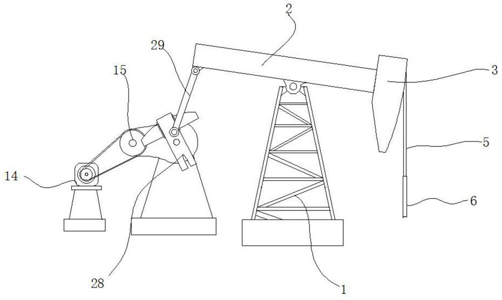
[0039] Please refer to Figure 1-9 As shown, a special pumping unit protection device for oil production engineering includes a motor 14, a reducer 15, a support frame 1 and an upper joint 4. A movable beam 2 is rotatably connected to the top of the support frame 1, and one end of the movable beam 2 is fixed with a The donkey head 3, the donkey head 3 is fixed with the sucker rod 6 through the wire rope 5;

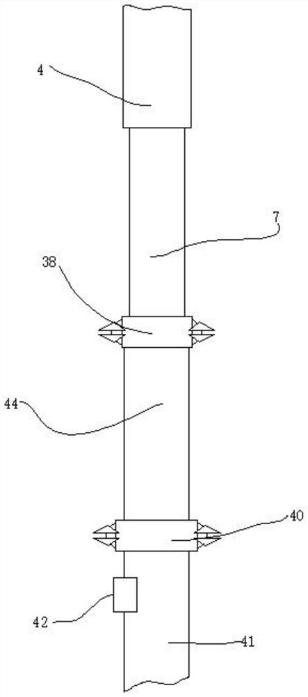
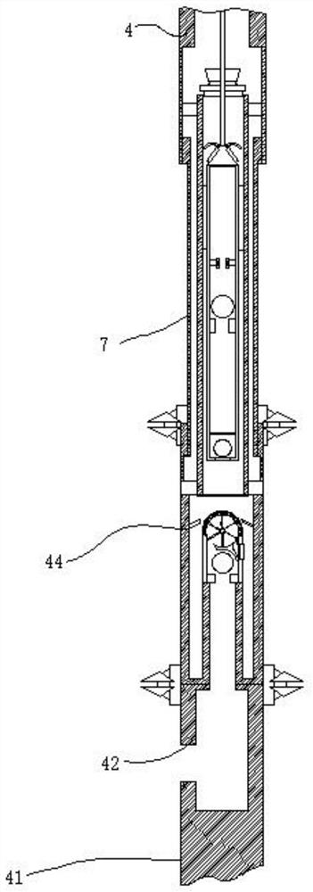
[0040] like Figure 7 As shown, the bottom end of the upper joint 4 of the present invention is communicated with an outer cylinder 7, and the bottom end of the outer cylinder 7 is provided with a fixed cylinder 44, the inner part of the outer cylinder 7 is provided with a pump cylinder 8, and the inside of the pump cylinder 8 slides with a plug Column 9, the bottom of the plunger 9 is provided with an oil inlet hole 10, and the bottom of the inner ...


PUM


Abstract

The invention provides a special oil pumping unit protection device for oil production engineering and a use method thereof. Comprising a motor, a speed reducer, a supporting frame and an upper connector, the top of the supporting frame is rotationally connected with a movable beam, a horse head is fixed to one end of the movable beam, a sucker rod is fixed to the horse head through a steel wire rope, the bottom end of the upper connector communicates with an outer cylinder, a fixed cylinder is arranged at the bottom end of the outer cylinder, and a pump cylinder is arranged in the outer cylinder; a plunger is arranged in the pump cylinder in a sliding mode, and an oil inlet hole is formed in the bottom of the plunger. According to the special oil pumping unit protection device for the oil production engineering and the using method thereof, oil drainage is prevented, the blowout prevention mechanism is arranged, the overflow condition caused by stratum energy can be effectively controlled, the sand content of crude oil is reduced, foreign matter deposition in a well can be prevented from blocking the bottom of an oil well pump, and the problem that foreign matter deposition in the well blocks the bottom of the oil well pump and a pipeline is solved; and therefore, the service life of the oil pump is prolonged.

Description

technical field [0001] The invention relates to the field of oil production engineering, in particular to a special pumping unit protection device for oil production engineering and a use method thereof. Background technique [0002] Oil production engineering is a general term for various engineering and technical measures taken to oil reservoirs through production wells and injection wells according to development goals in the process of oilfield development. The theory, engineering design method and implementation technology of various engineering technical measures of yield. The task of oil production engineering is to make oil and gas flow smoothly into the well through a series of engineering and technical measures that can act on the reservoir, and lift it to the surface efficiently for separation and metering; its goal is to increase the production of oil wells cost-effectively and crude oil recovery. [0003] Oil wells are holes drilled by drilling methods. Gener...

Claims


Application Information

Patent Timeline
Patent Type & Authority Applications(China)
IPC IPC(8): E21B43/00E21B43/38E21B37/08
CPCE21B43/127E21B43/38E21B43/35E21B37/08
Inventor 张谦沈霖柳邦郁张伟鹏秦世群
Owner 张谦
Why Eureka
Try Eureka