
Coated abrasive tool bonding strength detection equipment

A technology of bonding strength and testing equipment, which is applied in the direction of measuring devices, instruments, and mechanical devices, etc., can solve problems such as inability to detect strength, and achieve the effect of reasonable detection methods

Inactive Publication Date: 2022-08-09
江苏极冠智能机器科技有限公司
View PDF1 Cites 0 Cited by
  • Summary
  • Abstract
  • Description
  • Claims
  • Application Information

AI Technical Summary

Problems solved by technology

[0003] The disadvantage of the above-mentioned patents is that the detection of the adhesive strength of the coated abrasive must be processed according to the actual use requirements. For example, when using sandpaper for grinding, the manual grinding will stop after a period of time in actual use, or when grinding The heat generated by friction will make the contact between the user's hand and the sandpaper uncomfortable, and the user will stop grinding at this time, while the coated abrasive in the above patent is continuously rubbed when it is detected, because grinding will generate temperature, temperature It may affect the detection of the bonding strength of coated abrasives. Secondly, different strengths are applied according to the intensity of grinding during manual grinding, and the above-mentioned patent does not involve the disclosure of this part; in summary, the above-mentioned patents cannot be based on the actual use of sandpaper. Reasonable strength testing for the situation

Method used


Image

  • Coated abrasive tool bonding strength detection equipment
  • Coated abrasive tool bonding strength detection equipment
  • Coated abrasive tool bonding strength detection equipment

Examples


Embodiment Construction

[0022] The technical solutions in the embodiments of the present invention will be clearly and completely described below with reference to the accompanying drawings in the embodiments of the present invention. Obviously, the described embodiments are only a part of the embodiments of the present invention, but not all of the embodiments.

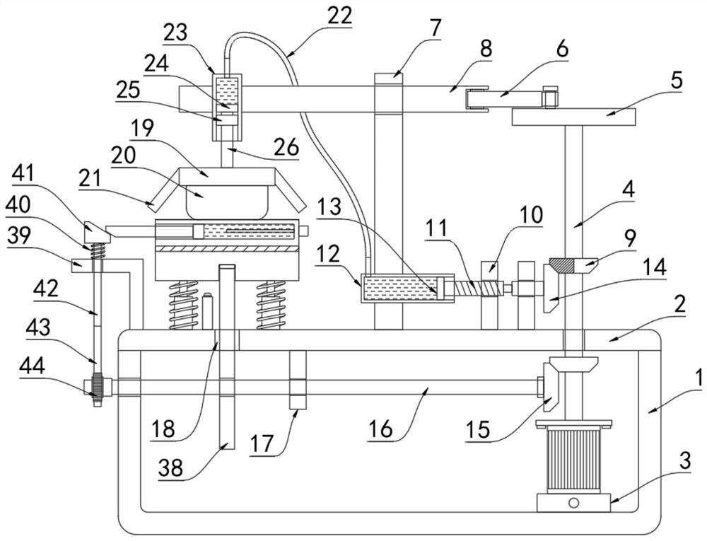
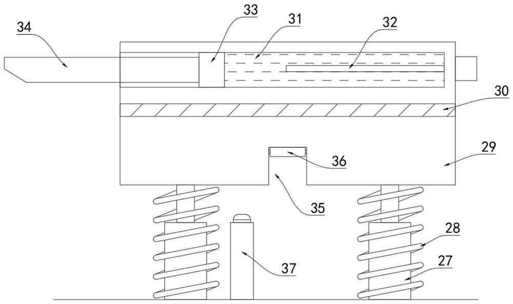
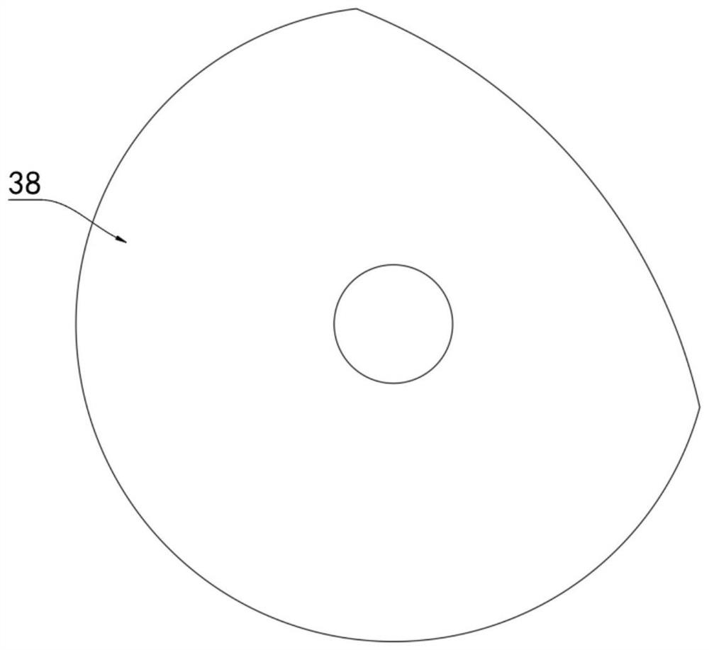
[0023] refer to Figure 1-4 , a coating abrasive bonding strength testing equipment, including a U-shaped seat 1, a mounting plate 2 is installed on the U-shaped seat 1, a motor 3 is installed on the U-shaped seat 1, and the motor 3 is a positive and negative motor; The output end is fixedly connected with a rotating rod 4, the rotating rod 4 penetrates through the mounting plate 2 and is rotatably connected with it, and the upper end of the mounting plate 2 is fixedly connected with a vertical plate 7 and a support block 10 arranged perpendicular to it, and the vertical plate 7 is provided with a sliding plate therethrough. The connected s...


PUM


Abstract

The invention discloses coated abrasive tool bonding strength detection equipment which comprises a U-shaped seat and is characterized in that a mounting plate is mounted on the U-shaped seat, a motor is mounted on the U-shaped seat, the output end of the motor is fixedly connected with a rotating rod, and the rotating rod penetrates through the mounting plate and is rotationally connected with the mounting plate; a vertical plate and two supporting blocks are fixedly connected to the upper end of the mounting plate, the vertical plate is perpendicular to the mounting plate, a sliding rod in sliding connection with the vertical plate is arranged on the vertical plate in a penetrating mode, a connecting rod mechanism is arranged between the sliding rod and the rotating rod, and a first piston cylinder is installed on the vertical plate in a penetrating mode. The device can simulate the actual manual polishing condition, the polishing condition under different pressures and the actual condition that polishing is stopped or intermittent polishing is carried out due to the fact that the coated abrasive tool generates heat during polishing, so that the device has more practical reference value in the detection of the bonding strength of the coated abrasive tool, the detection mode is more reasonable, and the detection efficiency is improved. And the method has more practical significance for evaluating the bonding strength of the coated abrasive tool.

Description

technical field [0001] The invention relates to the technical field of detection of coated abrasives, in particular to a detection device for the bonding strength of coated abrasives. Background technique [0002] The prior art discloses an application number CN202110625665.1 for detecting the bonding strength of a coated abrasive, including a bracket, wherein the bracket is slidably connected with a lift table and a lift drive assembly for driving the lift table to slide, the The lifting table is rotatably connected with a friction block; the support is rotatably connected with a rotating table, the rotating shaft of the rotating table and the rotating shaft of the friction block intersect vertically, and the rotating table is rotatably connected with a first roller for carrying the annular coated abrasives and the second roller, the rotating shafts of the first and second rollers are perpendicular to the rotating shaft of the rotary table; the rotating table is rotatably c...

Claims


Application Information

Patent Timeline
IPC IPC(8): G01N19/04
CPCG01N19/04
Inventor 唐木香黄爱卿
Owner 江苏极冠智能机器科技有限公司
Learn More