Starting impact current suppression method of inductive coupling energy transmission system

A start-up inrush current and energy transmission technology, which is applied in the control/regulation system, electric vehicle charging technology, output power conversion device, etc., can solve the problems of adding pre-charging circuits, multiple reactive power, and high project cost, and achieve reduction Heat generation, reducing reactive power loss, and low engineering cost

Pending Publication Date: 2022-08-09
INST OF ELECTRICAL ENG CHINESE ACAD OF SCI
View PDF1 Cites 0 Cited by
  • Summary
  • Abstract
  • Description
  • Claims
  • Application Information

AI Technical Summary

Problems solved by technology

However, this method will generate more reactive power and reduce system efficiency. At the same time, for the inductively coupled energy transfer system with frequency splitting phenomenon, it is easy to cause system instability.
In the Chinese invention patent CN202011224629.6 "Electromagnetic Induction Wireless Power Transmission System and Its Starting Current Impulse Suppression Method", an additional pre-charging circuit is used to precharge the filter capacitor on the secondary side to suppress the starting inrush current, but this method An additional pre-charging circuit is added, and the engineering cost is high

Method used


Image

  • Starting impact current suppression method of inductive coupling energy transmission system
  • Starting impact current suppression method of inductive coupling energy transmission system
  • Starting impact current suppression method of inductive coupling energy transmission system

Examples


Embodiment Construction

[0034] In order to make the objectives, technical solutions and advantages of the present invention clearer, the present invention will be further described in detail below with reference to the accompanying drawings and embodiments. It should be understood that the specific embodiments described herein are only used to explain the present invention, but not to limit the present invention. In addition, the technical features involved in the various embodiments of the present invention described below can be combined with each other as long as they do not conflict with each other.

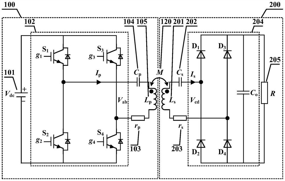
[0035] like figure 1 As shown, the embodiment of the inductively coupled energy transmission system of the present invention is based on a string-to-series compensation circuit, and consists of the primary side 100 of the inductively coupled energy transmission system and the secondary side 200 of the inductively coupled energy transmission system. The primary side 100 of the inductively coupled en...


PUM


Abstract

The invention provides a starting impact current suppression method for an inductive coupling energy transmission system, which comprises the following steps of: firstly, establishing a mathematical model of the inductive coupling energy transmission system, calculating and setting the starting time ts of the system, selecting a proper triangular carrier frequency f, and then changing the duty ratio D according to the rule of a nonlinear saturation function within the starting time ts, so as to suppress the starting impact current of the inductive coupling energy transmission system. The method comprises the steps that a high-frequency inverter is connected with a triangular carrier wave and is compared with the triangular carrier wave to obtain a switching function d, when the switching function d is a logic high level, the high-frequency inverter adopts phase-shift control with the phase-shift angle being 0 degree, and when the switching function d is a logic low level, the high-frequency inverter stops working, and then the starting impact current of the inductive coupling energy transmission system is restrained. When the duty ratio D changes according to the rule of a nonlinear saturation function, the system oscillation time is obviously shortened, and the amplitude is reduced.

Description

technical field [0001] The invention belongs to the field of wireless power transmission, and in particular relates to a start-up impulse current suppression method of an inductively coupled energy transmission system. Background technique [0002] The inductively coupled energy transfer system is a new power supply method that transfers electrical energy to the load in a non-contact manner through the principle of electromagnetic induction. Because it does not require physical connection, it has the advantages of safety, reliability and environmental friendliness. Therefore, this technology has been widely used. It is suitable for low-power occasions such as electronic products and medical equipment, as well as high-power occasions such as electric vehicles and rail transit. [0003] In high-power applications, the inductively coupled energy transmission system needs to transmit large power to the load, so the system will generate a large start-up inrush current during the ...

Claims


Application Information

Patent Timeline
Patent Type & Authority Applications(China)
IPC IPC(8): H02M1/00H02M1/088H02M1/32H02M7/48H02M3/335H02J50/10
CPCH02M1/0038H02M1/0058H02M1/088H02M1/32H02M7/48H02M3/33569H02J50/10Y02T90/14
Inventor 史黎明杨继鑫段正刚唐文京范满义
Owner INST OF ELECTRICAL ENG CHINESE ACAD OF SCI
Why Eureka
Try Eureka