
Method of inhibiting coke deposition in pyrolysis furnaces

A technology of coke deposition and pyrolysis furnace, which is applied in the direction of non-catalytic thermal cracking, cracking, petroleum industry, etc., and can solve problems that have not been realized

Inactive Publication Date: 2004-08-04
NALCOEXXON ENERGY CHEM
View PDF12 Cites 6 Cited by
  • Summary
  • Abstract
  • Description
  • Claims
  • Application Information

AI Technical Summary

Problems solved by technology

The benefit of using excess sulfur over phosphorus has not been recognized in the prior art

Method used

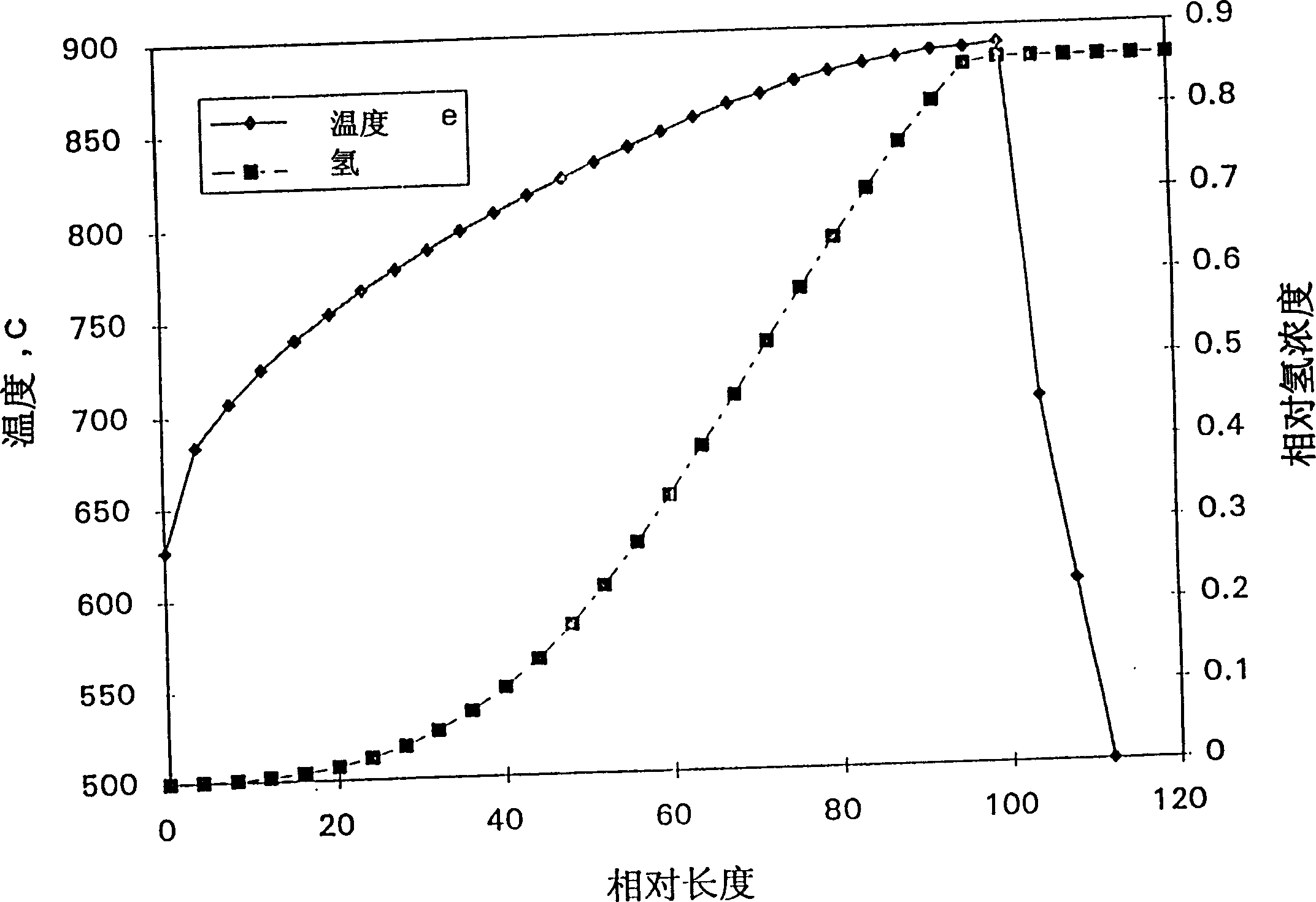
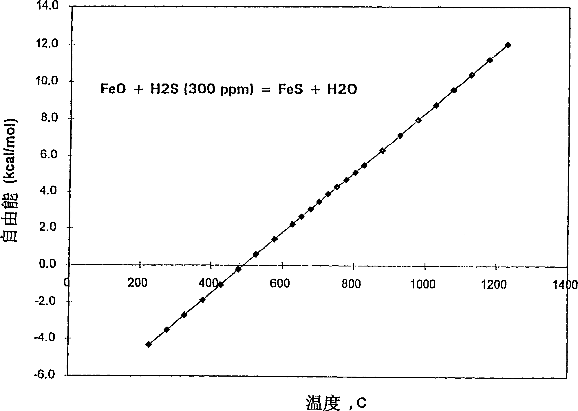
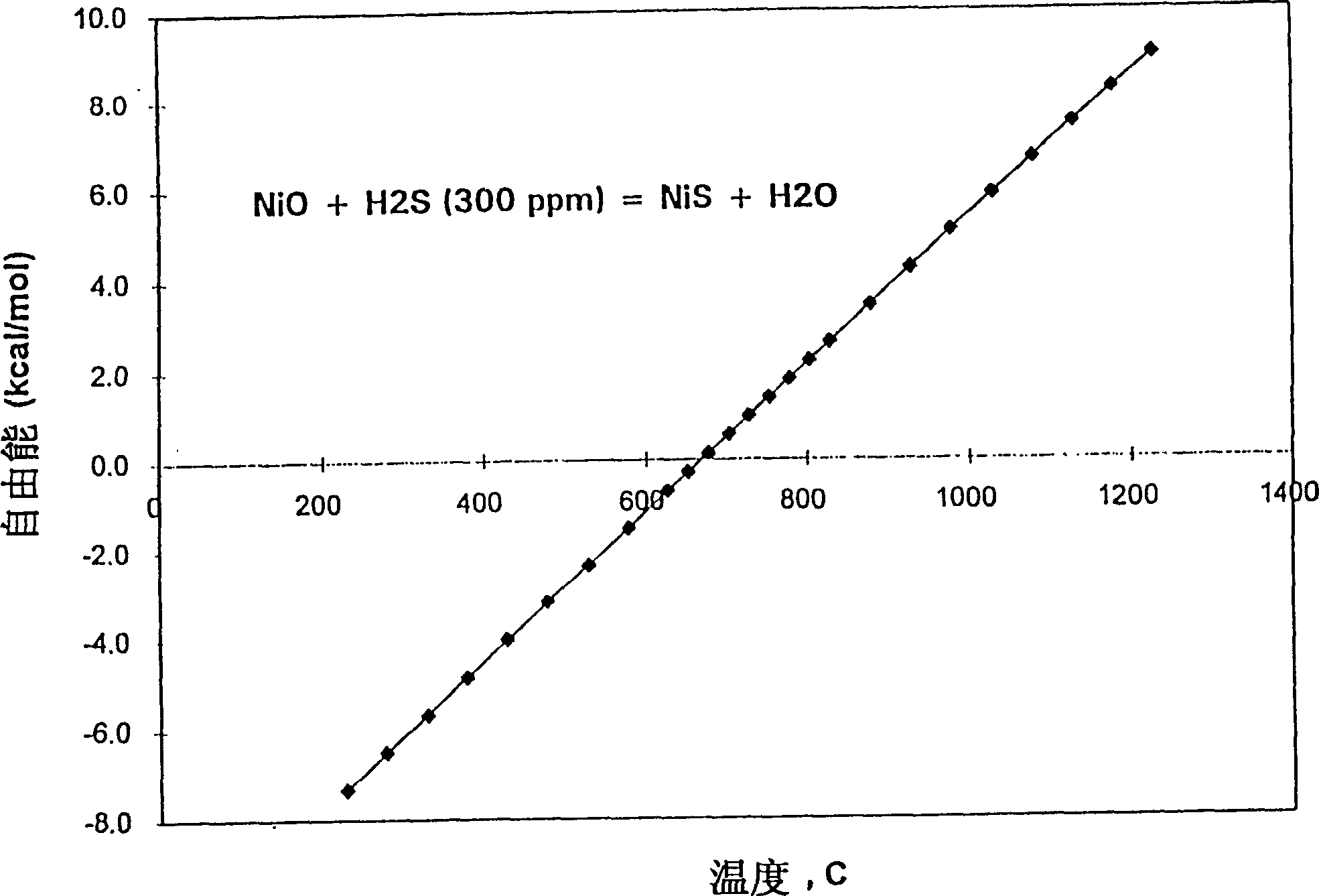

Image

  • Method of inhibiting coke deposition in pyrolysis furnaces
  • Method of inhibiting coke deposition in pyrolysis furnaces
  • Method of inhibiting coke deposition in pyrolysis furnaces

Examples


Embodiment 1

[0053] Dimethyl disulphide (DMDS) and hexamethyldisiloxane were separately mixed into the 5% TPP solution as co-additives. The amount of each co-additive is adjusted to obtain an overall S:P or Si:P atomic ratio. These solutions were then tested for sulfur or silicon versus pH 3 The impact of formation. The results are summarized in Table 1 below.

[0054] Table 1

[0055] Additive Relative pH 3 Generation speed

[0056] Only TPP 100

[0057] TPP and DMDS68

[0058] TPP and hexamethyldisiloxane 94

[0059] As shown in Table 1, when DMDS and TPP are present simultaneously, PH 3 The production was significantly reduced, indicating that DMDS actively participates in surface interactions and effectively competes with TPP for surface active sites.

Embodiment 2

[0061] In TPP-containing solutions, when DMDS was replaced by propyl disulfide (PDS), pH 3 production was significantly reduced, indicating that the pH 3 The reduction in formation is a general phenomenon for sulfur species.

Embodiment 3

[0063] When 1% PDS is added to a solution containing 1% TPYPO, the pH 3 50% reduction in generation, indicating reduction of pH by sulfur species 3 Suitable for all phosphorus compounds.


PUM


Abstract

A method is disclosed for reducing coke deposition in a pyrolysis furnace which comprises treating the pyrolysis furnace with a combination of sulfur- and phosphorus-containing compounds having a total sulfur to phosphorus atomic ratio of at least 5.

Description

field of invention [0001] This invention relates generally to ethylene production, and more particularly to a method of inhibiting coke deposition in pyrolysis furnaces. Background of the invention [0002] Ethylene production requires the thermal cracking of various gaseous and liquid petroleum feedstocks using pyrolysis furnaces (also known as steam crackers or ethylene furnaces) to obtain ethylene and other useful products. Gaseous feeds to pyrolysis furnaces generally include ethane, propane, butane, and mixtures thereof. The liquid raw materials of the pyrolysis furnace generally include naphtha, kerosene, gas oil and other petroleum distillates. [0003] In the temperature range of 700-1000°C, the petroleum feedstock is cracked in the tubular reactor of the pyrolysis furnace. During cracking reactions, steam is generally injected into the feed to control some unwanted reactions / processes, such as coke formation. In typical operation of a pyrolys...

Claims


Application Information

Patent Timeline
Patent Type & Authority Patents(China)
IPC IPC(8): C10G9/16
CPCC10G9/16
Inventor 童友东迈克尔·K·波因代克斯特
Owner NALCOEXXON ENERGY CHEM
Learn More