Ray testing equipment and ray testing method

A technology of ray inspection and ray, applied in the field of non-destructive inspection equipment, can solve the problem of high hardware and software costs

Inactive Publication Date: 2005-01-19
SHIMADZU SEISAKUSHO CO LTD
View PDF0 Cites 0 Cited by
  • Summary
  • Abstract
  • Description
  • Claims
  • Application Information

AI Technical Summary

Problems solved by technology

Therefore, conventional devices have a problem that large-scale image processing must be performed in order to realize a high-speed inline system, and the hardware and software costs of the device are high

Method used


Image

  • Ray testing equipment and ray testing method
  • Ray testing equipment and ray testing method
  • Ray testing equipment and ray testing method

Examples


Embodiment Construction

[0018] The embodiments of the present invention will be described below with reference to the drawings.

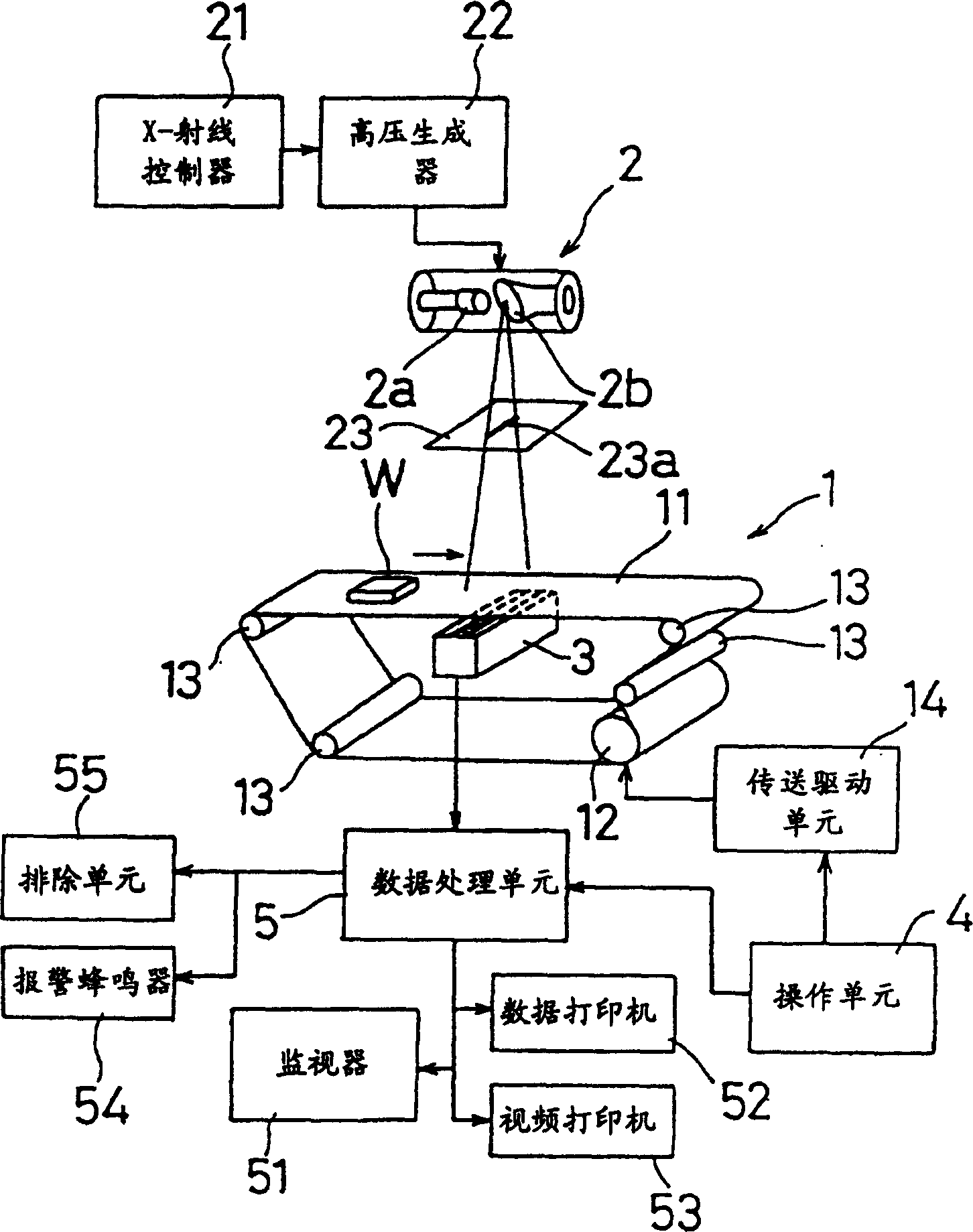
[0019] figure 1 It is a diagram for explaining the structure of the radiographic inspection apparatus according to the embodiment of the present invention, and shows a schematic diagram showing the mechanical structure of the main part of the embodiment and a block diagram showing the system control pipeline of the main part of the embodiment.

[0020] The inspected object W is placed on the endless belt 11 of the conveying system 1 and is conveyed at a constant speed. Above the transmission system 1, the X-ray tube 2 is arranged in a position where the X-ray optical axis is vertically downward. In addition, the one-dimensional X-ray detector 3 is vertically arranged under the X-ray tube 2 in a manner facing the X-ray tube 2, wherein the circulating belt 11 of the transmission system 1 is inserted between the X-ray tube 2 and the one-dimensional X-ray detector Between 3.

[...


PUM


Abstract

A radiation inspection apparatus calculates the difference between pixel data of each pixel, which is outputted from radiation detector 3, and pixel data of each of surrounding pixels thereof. Then, the apparatus obtains a total of circumference length of an object to be inspected WA by totalizing the number of pixels, the gray level data obtained by difference processing correspondingly to each of which is within a predetermined gray level range of gray level profile from XL to XH. Thus, the apparatus determines from the value of the total of the circumference length of the object whether or not a crack or a nick occurs in the object.

Description

Technical field [0001] The invention relates to a non-destructive inspection equipment or method for inspecting drugs and food. More specifically, the present invention relates to a radiographic inspection device and a radiographic inspection method suitable for inspecting a packaging object whose inside cannot be viewed with visible light due to packaging materials for cracks or cracks. Background technique [0002] So far, as for equipment for inspecting cracks or rips in packaged food, inspection equipment using visible light or infrared light is well known. Such inspection equipment using visible light or infrared light usually emits visible light or infrared light to the packaged object to be inspected, and then receives the light reflected or transmitted by the object by using a CCD camera. As a result, the inspection device acquires image information about the inside of the package, and determines whether the object contained in the package has abno...

Claims


Application Information

Patent Timeline
Patent Type & Authority Patents(China)
IPC IPC(8): G01B15/00G01B15/04G01N23/04G01N23/10G01T1/00G06T1/00G06T7/60
CPCG01N23/04G01B15/04
Inventor 泽田良一
Owner SHIMADZU SEISAKUSHO CO LTD
Why Eureka
Try Eureka