Dath monitoring in optical communication systems

A technology of optical communication and line, applied in the direction of optical multiplexing system, transmission system, multiplexing communication, etc., which can solve the problem of undetectable optical fiber

Inactive Publication Date: 2004-07-07
TELEFON AB LM ERICSSON (PUBL)
View PDF0 Cites 0 Cited by
  • Summary
  • Abstract
  • Description
  • Claims
  • Application Information

AI Technical Summary

Problems solved by technology

Therefore, a broken fiber in this fiber section may not be detected

Method used


Image

  • Dath monitoring in optical communication systems
  • Dath monitoring in optical communication systems
  • Dath monitoring in optical communication systems

Examples


Embodiment Construction

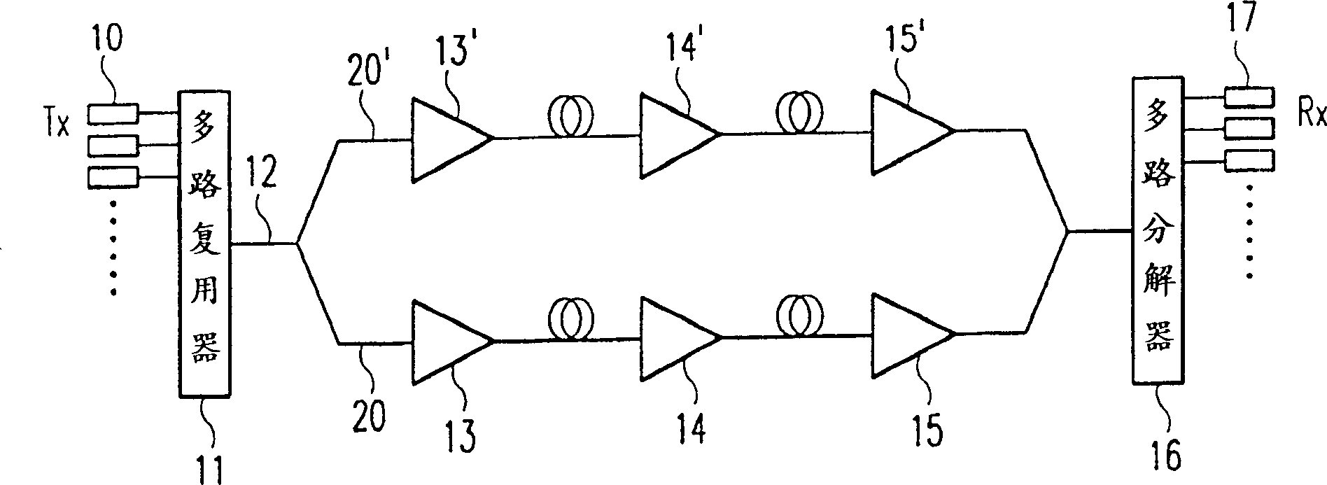
[0019] figure 1 The WDM point-to-point system in includes WDM transmitters 10, each transmitting a modulated payload data signal at a carrier wavelength to a multiplexer 11, which then combines the signals onto a single optical fiber 12 . The fiber 12 is then split into two lines 20, 20' by a 1X2 or 2X2 fiber coupler. The multiplexed signals on each line are thus propagated in parallel through the first optical amplifier, the power amplifiers 13 and 13', through the fiber amplifiers 14 and 14' and through the final or preamplifiers 15 and 15', respectively, as For convenience of example only one of these amplifiers in each line is shown. The fibers of the two lines 20 and 20 ′ are then recombined before entering the demultiplexer 16 , which splits the signals by wavelength and passes them on to the WDM receiver 17 . Optical power amplifiers 13 and 13' and line amplifiers 14 and 14' may be formed by any suitable amplifiers, including but not limited to regenerative optical r...


PUM


Abstract

An optical communication line having optical fibre amplifiers including a pump laser can be configured to suppress the transmission of optical signals, for example when used as a duplicate line for redundancy, by reducing the power of the pump laser. In order that the portion of the line downstream of the amplifier can be monitored for fibre breaks causing only negligible crosstalk with a parallel working line and with the elimination the risk of mistaking reflections from a working line for light emitted by the standby amplifier, light emitted by the standby amplifier is modulated by a low frequency control tone. Preferably the pump laser current is modulated by a low frequency signal. The modulated laser light causes modulation of the ASE generated in the amplifier to create a control tone. Monitoring means disposed at the end of the optical line detect this control tone and use this as the criteria for a functional connection downstream of the amplifier.

Description

technical field [0001] The present invention relates to fiber optic communication lines designed to operate in a standby manner, attenuating or substantially eliminating signal transmission, but still capable of monitoring for cable breaks or other failures. In particular, the present invention relates to optical systems in which redundant fiber optic cables are provided for added protection, and more particularly to wavelength division multiplexed systems. The present invention further relates to an optical fiber amplifier suitable for use in an optical communication line designed to operate in a standby state, and a method for monitoring the operation of an optical communication line designed to operate in a standby state. Background technique [0002] In many optical communication applications, it is important to at least temporarily block signal transmission over individual lines. One application is the duplication of optical links connecting end stations to enable work...

Claims


Application Information

Patent Timeline
IPC IPC(8): H01S5/0683H01S5/50H04B10/032H04B10/07H04B10/291H04B10/293
CPCH04B10/2912H04J14/029H04B10/2933H04B10/07H04J14/0289H04J14/0279H04B10/032
Inventor F·利登J·桑德尔S·温斯特兰德M·厄贝里
Owner TELEFON AB LM ERICSSON (PUBL)
Why Eureka
Try Eureka