Microcomputer input and output circuit

A technology of input and output circuits and microcomputers, which is applied to circuit devices, electronic circuit testing, digital circuit testing, etc., and can solve the problems of overlapping voltage division values, complex arithmetic processing, and difficulty in specifying the range of voltage division values ​​for each operation information.

Inactive Publication Date: 2019-12-17
SUMITOMO WIRING SYST LTD
View PDF7 Cites 0 Cited by
  • Summary
  • Abstract
  • Description
  • Claims
  • Application Information

AI Technical Summary

Problems solved by technology

[0006] However, the divided voltage value obtained by the above method becomes a wide value due to the fluctuation of the power supply voltage or each resistor, so there is overlap of divided voltage values ​​indicating external resistors corresponding to a plurality of operation information, and it is difficult to specify and display each operation information. (External resistance) in the case of the range of the divided voltage value
In order to solve the above problems, for example, adding a constant voltage IC to reduce the fluctuation of the divided voltage value by making the power supply voltage constant voltage can be considered, but it will increase the cost and cannot be said to be an effective countermeasure.
As another countermeasure, it is also conceivable to monitor the power supply voltage and calculate the threshold value of the divided voltage value of each external resistor by arithmetic processing for each power supply voltage without overlapping to determine the selected operation information. Complicated calculation processing is required, so it cannot be said to be an effective countermeasure, and there is still room for improvement

Method used


Image

  • Microcomputer input and output circuit
  • Microcomputer input and output circuit
  • Microcomputer input and output circuit

Examples


Embodiment Construction

[0029] Hereinafter, embodiments of the present invention will be described with reference to the drawings.

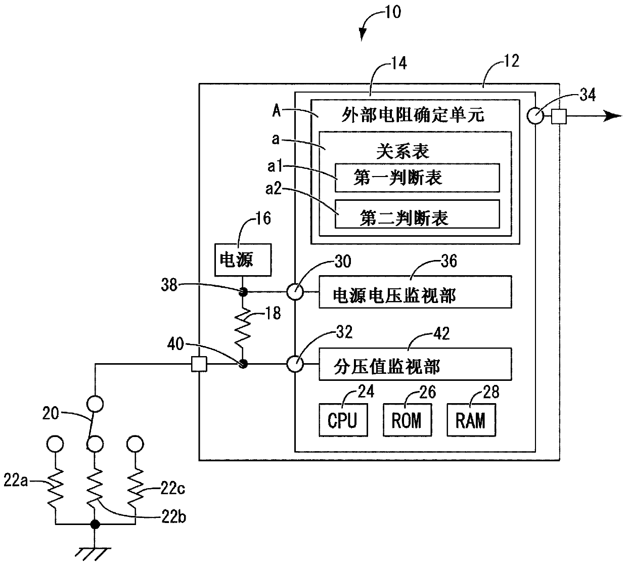
[0030] figure 1 A microcomputer input / output circuit 10 configured as one embodiment of the present invention is shown. In this embodiment, a microcomputer input-output circuit 10 to which the present invention is applied is exemplified in an on-vehicle main body ECU (Electronic Control Unit: electronic control unit) 12 that controls various control objects in a main system such as a power window of a vehicle. case is described as an example.

[0031] Such as figure 1 As shown, the microcomputer input and output circuit 10 includes a microcomputer 14, a power supply 16, a power supply resistor 18, and a plurality of (three in this embodiment) external circuits provided outside the vehicle-mounted main body ECU 12 and connected to the vehicle-mounted main body ECU 12 via a switch 20. Resistors 22a~c are formed.

[0032] The microcomputer 14 includes a CPU (Central Pr...


PUM


Abstract

Provided is a microcomputer input / output circuit with a new structure that can stably determine operation information corresponding to a divided voltage value without adding components that increase cost or complicated arithmetic processing. It is provided with: a microcomputer (14); a power source (16); a power source resistor (18), one end of the power source resistor (18) is connected to the power source (16), and the other end of the power source resistor (18) is connected to the power source (16) via a switch (20) The grounded external resistors (22a, 22b, 22c) are connected alternatively; the power supply voltage monitoring part (36) can monitor the power supply voltage; the divided voltage value monitoring part (42) can monitor the power supply resistance (18) and the selected A divided voltage value divided by the external resistors (22a, 22b, 22c); and an external resistance determination unit (A), which is included in the divided voltage value range corresponding to each of the external resistors (22a, 22b, 22c) according to the above-mentioned divided voltage value Which of the external resistors (22a, 22b, 22c) selected by the switch (20) is determined, and the external resistance determination unit (A) changes the voltage division value range based on the power supply voltage obtained by the power supply voltage monitoring unit (36) .

Description

technical field [0001] The invention relates to a microcomputer input and output circuit. Background technique [0002] Conventionally, a microcomputer input / output circuit has been used as a means for controlling the operation of various electrical equipment. Operation information of the electrical equipment is input to the microcomputer, and the electrical equipment operates based on control signals output from the microcomputer. For example, in Japanese Patent Application Laid-Open No. 10-257791 (Patent Document 1) figure 1 Among them, by switching the P / W switch to up (UP) and down (DOWN), the operation information of the power window is input to the microcomputer, and the control signal for driving the power window is output to the motor based on the input information. [0003] However, in the conventional microcomputer input-output circuit described in the above-mentioned Patent Document 1, if figure 1 As shown, the input terminals of the microcomputer are required f...

Claims


Application Information

Patent Timeline
Patent Type & Authority Applications(China)
IPC IPC(8): H02J1/00B60R16/02G01R31/319G05F1/10G06F1/28
CPCG01R31/319G05F1/10G06F1/28G05F1/12G06F1/305B60R16/03B60R16/02
Inventor 高桥宏彰
Owner SUMITOMO WIRING SYST LTD
Why Eureka
Try Eureka