Means for controlling target erosion and sputtering in magnetron

A magnetron and magnet device technology, applied in sputtering coating, discharge tube, ion implantation coating, etc., can solve the problems of weakening magnetic field strength, electron loss, plasma instability, etc., to eliminate uneven consumption, cost and maintenance time reduction, less prevention and maintenance effect

Inactive Publication Date: 2005-04-06
BEKAERT ADVANCED COATINGS
View PDF5 Cites 1 Cited by
  • Summary
  • Abstract
  • Description
  • Claims
  • Application Information

AI Technical Summary

Problems solved by technology

As explained in WO96 / 21750, the method according to US 5,364,518 has the disadvantage that the widening of the racetrack at the ends may lead to instability of the plasma due to the weakened magnetic field strength and electron losses caused by the wider magnet spacing
This known method is derived from the assumption that electron losses at the end corners of the runway cannot be avoided

Method used


Image

  • Means for controlling target erosion and sputtering in magnetron
  • Means for controlling target erosion and sputtering in magnetron
  • Means for controlling target erosion and sputtering in magnetron

Examples


Embodiment Construction

[0036] The present invention will be described with reference to particular embodiments and certain drawings but the invention is not limited thereto but only by the claims. The drawings described are only schematic and not restrictive.

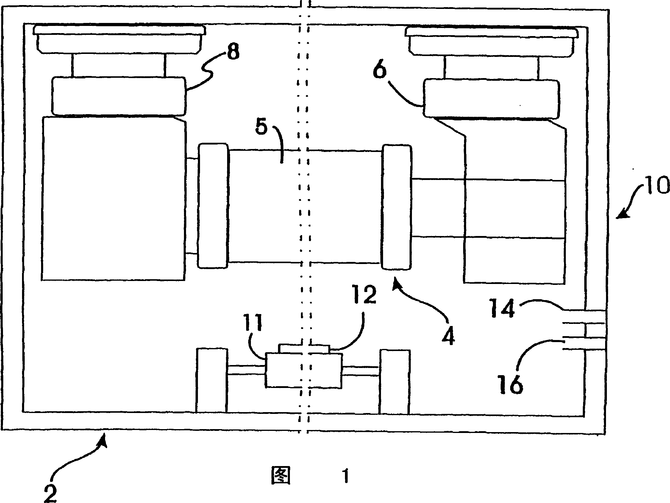
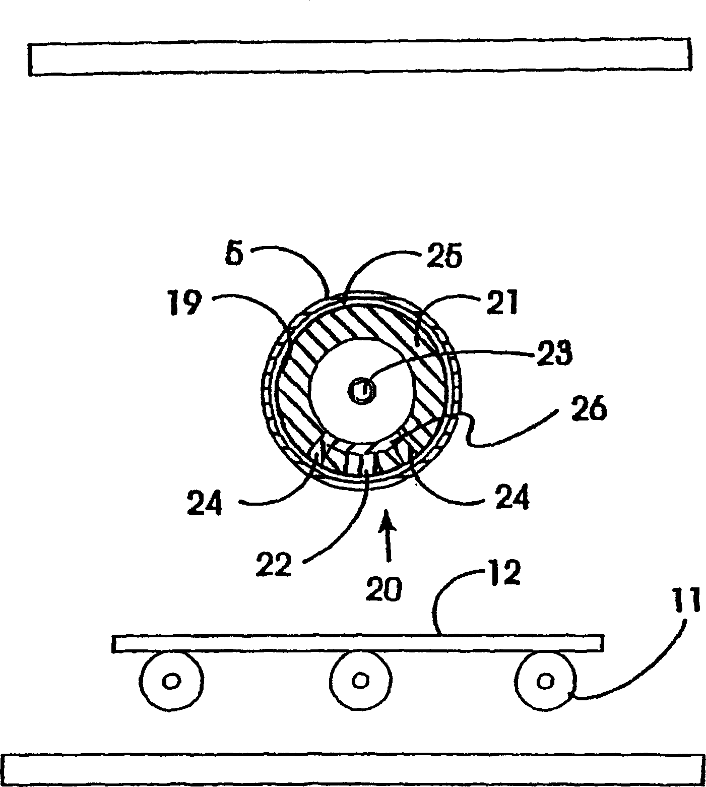
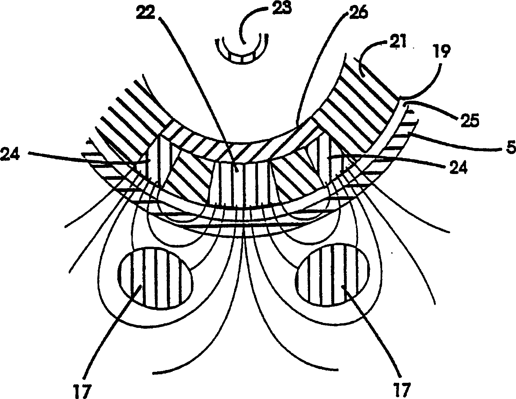
[0037] Figures 1, 2a and 2b are schematic illustrations of a sputtering magnetron 10 according to the present invention. Figure 1 is a side view of a target 4 in a vacuum chamber 2, while Figure 2a is a cross-sectional view through target 4. Figure 2b From Figure 2a Partial enlarged view of target 4. The vacuum chamber 2 preferably includes a movable, cylindrical rotating target 4 . The target 4 can be connected to the target 4 through a feeder 6 by any suitable driving means, for example, an electric motor or a hydraulic press or the like. The other end of the target 4 is supported by another feeder 8 for cooling liquid and power supply (not shown) of the target 4 into the vacuum chamber 2 . The target 4 may be a tube consisting of th...


PUM


Abstract

A sputtering magnetron with a rotating cylindrical target and a stationary magnet assembly (22, 24*) is described, said magnet assembly (22, 24*) being adapted to produce an elongate plasma race-track on the surface of said target, said elongate race-track having substantially parallel tracks over a substantial portion of its length and being closed at each end by end portions (22'), wherein the spacing between the tracks of said race-track is increased locally to materially effect sputtering onto a substrate. The increase in spacing may be at the end portions or along the parallel track portion. The increase in spacing may provide more even erosion of the target beneath the end portions of the race-track, provide more even coatings on the substrate.

Description

field of invention [0001] The present invention relates to an improved rotating cathode magnetron suitable for sputtering or reactive sputtering from a tubular cathode target onto a stationary or moving substrate and a method of operation of the same. The magnetic arrangement of the magnetron of the present invention is arranged in such a way that the localized variation of the plasma racetrack provides new advantages for the sputtering process. Furthermore, the novel magnetic device is particularly suitable for curved structures. technical background [0002] In the standard non-reactive metal sputtering mode, sputtering with planar magnetrons is known. The biggest trouble is the formation of an erosion trench in the target material, which, with the plasma that forms it, is often referred to as a "race track." The non-uniform erosion cross section is essentially related to the shape of the magnet underlying the target. As a result, the target should be replaced before th...

Claims


Application Information

Patent Timeline
Patent Type & Authority Patents(China)
IPC IPC(8): C23C14/35H01J37/34
CPCH01J37/3405C23C14/34
Inventor W·德博斯彻H·列文斯
Owner BEKAERT ADVANCED COATINGS
Why Eureka
Try Eureka