
Double-mesh reticulate ceramic roller and its laser carving process

A technology of laser engraving and ceramic mesh, which is applied in laser welding equipment, rotary printing machines, printing, etc., can solve the problems of large ink consumption, easy printing white spots, and affecting the quality of printed products, so as to save ink and achieve uniform color Vividness, the effect of reducing the number of white spots

Inactive Publication Date: 2005-06-01
GUANGDONG BRIGHTAS LASER SCI & TECH
View PDF0 Cites 3 Cited by
  • Summary
  • Abstract
  • Description
  • Claims
  • Application Information

AI Technical Summary

Problems solved by technology

When using this kind of ceramic anilox roller with a single mesh structure to print products, printing white spots are prone to appear, which affects the quality of printed products, and the ink consumption is large

Method used


Image

  • Double-mesh reticulate ceramic roller and its laser carving process
  • Double-mesh reticulate ceramic roller and its laser carving process
  • Double-mesh reticulate ceramic roller and its laser carving process

Examples


Embodiment 1

[0018] Example one: such as Figure 4 As shown, the present invention proposes a method for engraving a double-mesh ceramic anilox roller by using a single original laser beam. The original laser beam 10 is generated by laser A, and the original laser beam 10 is divided into A laser beam by a beam splitter 17 11 and B laser beam 12;

[0019] The A laser beam 11 after passing through the beam splitter 17 continues to advance in the direction of the original laser beam 10, passes through the A hole mold 14 to change the size and shape, and then passes through the full transmission part of the full transmission and reflection combination mirror 133, and is directed to the focusing mirror 16;

[0020] The B laser beam 12 that changes its direction through the beam splitter 17 changes its direction through the total mirror 131, changes its size and shape through the B-hole mold 15, and then passes through the total reflection part of the total reflection mirror 132 and the total transm...

Embodiment 2

[0022] Embodiment two: such as Figure 5 As shown, a method for engraving a double-mesh ceramic anilox roller with two original laser beams is proposed. The two original laser beams can be generated by two lasers or one laser.

[0023] The A laser beam 11 generated by the A laser passes through the A hole mold 14 to shape the shape of the hole to be engraved, and then passes through the 45° total mirror 134 to change the direction, and then shoots to the focusing mirror 16.

[0024] The B laser beam 12 generated by the B laser passes through the B hole mold 15 to shape the shape of the hole to be engraved, and then changes the direction through the 45° total mirror 131 and shoots to the focusing mirror 16.

[0025] The A laser beam 11 and the B laser beam 12 are focused on the ceramic layer 2 of the roller body 1 through the same focusing lens 16, and two points are carved at the same time to respectively engrave meshes with their own characteristics.

[0026] Through automatic con...


PUM

PropertyMeasurementUnit
depthaaaaaaaaaa

Abstract

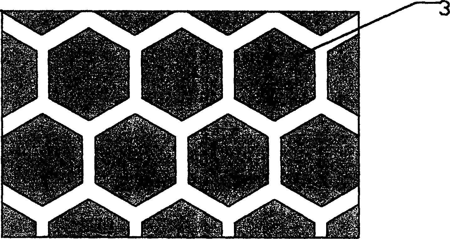
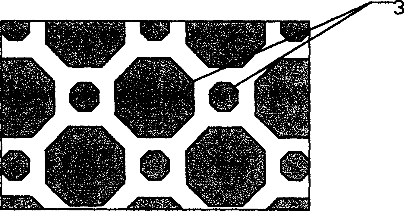
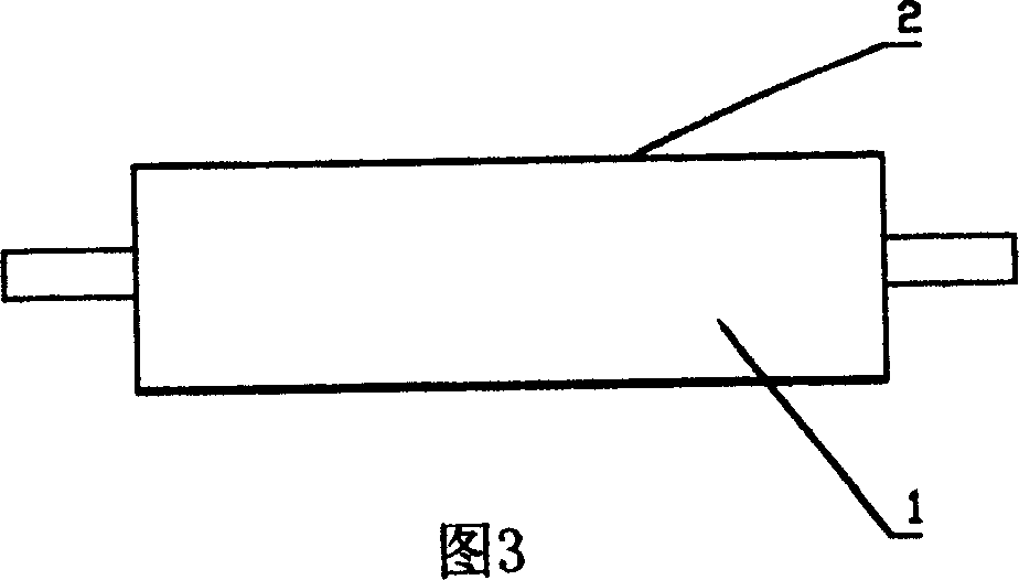
The present invention relates to a double-mesh ceramic textured roller and its manufacturing method. On the ceramic layer of roller body of said textured roller two types of meshes which are regularly arranged are set, and the form, size and depth of meshes of said two types are different. The production method of said textured roller incldues the following steps: making two laser beams simulataneously and respectively pass through pass die to change its form and size, then pass through same focusing lens and focus on two points of ceramic layer of the roller obdy to make engraving, utilizingautomatic control of transmitting frequency and energy of the laser beam and movement of ceramic roller or laser device so as to continuously engrave meshes with a certain arrangement regularity and proper depth, and the form of meshes can have various ones, so that it can raise printing quality.

Description

Technical field [0001] The invention relates to the core components of a flexographic printing machine, a packaging printing machine, a coating machine and a glazing machine, in particular to a ceramic anilox roller and a manufacturing method thereof. Background technique [0002] The anilox roller is the core component of flexographic printing presses, packaging printers, coating machines, glazing machines, etc. Its function is to accurately quantify ink or glue or solvents on the printing plate or substrate. The pros and cons of quality have a great influence on the quality of printed matter. The currently used anilox rollers are divided into two categories: metal anilox rollers and ceramic anilox rollers. Compared with ceramic anilox rollers, metal anilox rollers have poor wear resistance and short service life, making it difficult to engrave high-line counts (generally The anilox rollers below 400 lines have been gradually replaced by ceramic anilox rollers. [0003] The stru...

Claims


Application Information

Patent Timeline
Patent Type & Authority Patents(China)
IPC IPC(8): B23K26/36B41C1/05B41F13/08B41F23/08
Inventor 史贤彬姚志东李士俊朱继谋洪觉宏梁炳赞
Owner GUANGDONG BRIGHTAS LASER SCI & TECH
Learn More