Screening machine

A screening machine and screen basket technology, which is applied in the fields of filter screen, textile and paper making, solid separation, etc., can solve problems such as non-design, and achieve the effects of improving efficiency, reducing speed, high output and separation performance

Inactive Publication Date: 2005-06-08
ANDRITZ AG
View PDF0 Cites 3 Cited by
  • Summary
  • Abstract
  • Description
  • Claims
  • Application Information

AI Technical Summary

Problems solved by technology

[0006] The present invention is based on the observation that hitherto conventional airfoil shapes of the blade surfaces approaching the screen basket, in particular the planned gap between the blade and the screen basket at the guide section of the blade reduction, it is not an optimal design, either in terms of mechanical and energy efficiency, or with regard to the efficiency of the separation process, flow rate and separation performance

Method used


Image

  • Screening machine
  • Screening machine
  • Screening machine

Examples


Embodiment Construction

[0033] Such as figure 1 with 2As shown, respectively represent the schematic diagram of the horizontal cross section and the vertical cross section of the screening machine 100, the screening machine includes a housing 5 with an inlet 51 and an outlet 52, the inlet 51 is used for the entry of the screening material suspension, and the outlet 52 is used for For receiving pulp from which impurities have been removed. An outlet 53 or similar structure is provided at the bottom of the housing 5 for discharging impurities separated from the screening material. In the inner chamber 500 of the generally barrel-shaped or cylindrical housing 5, a cylindrical screen basket 2 is coaxially arranged, and the screen basket 2 has a circular or slot-type screening aperture 204 for clean pulp The suspension is passed through. Inside the inner chamber 200 of the screen basket 2 there is arranged a rotor 300 mounted on a central support on a shaft 381 driven by an electric motor 6, the rotor ...


PUM


Abstract

The assembly to sort wood and cellulose materials, for the production of paper and cardboard, has paddles rotating within a sieve body with a structured radial gap (ar) between the paddle and sieve surfaces. An assembly to sort wood and cellulose materials, comprises paddles rotating within a 
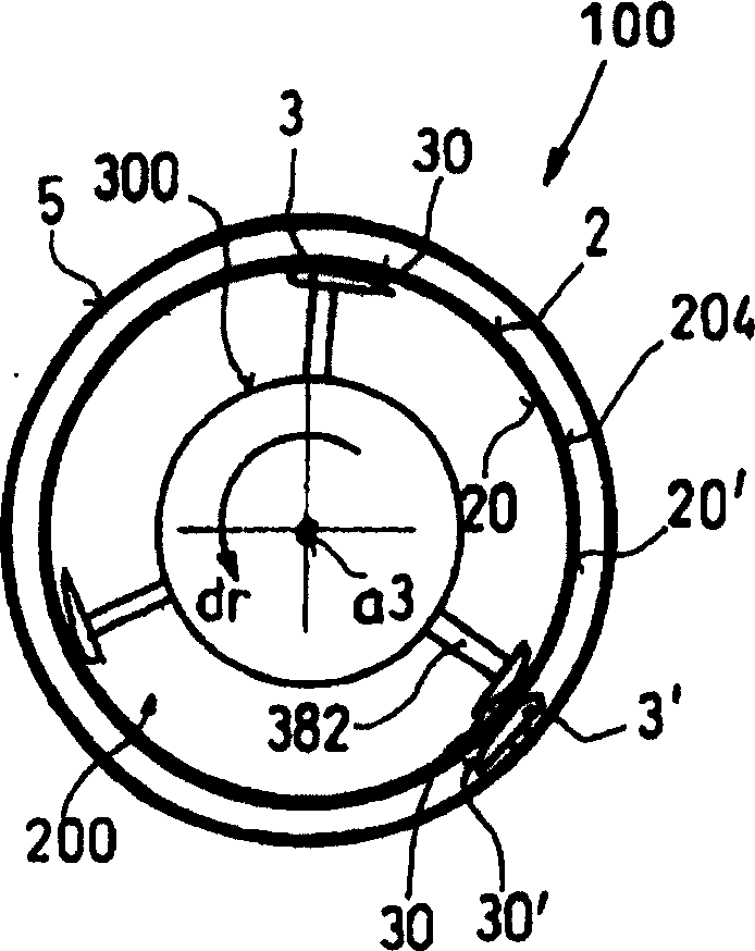
sieve body (2), has a radial gap between the leading end (31) of the paddles in the direction of rotation (dr) and especially the leading end point or leading edge (310) of the paddle surface (30) towards the sieve, and the facing surface (20) of the sieve body, with a minimum gap (arv) at the leading end and an increased maximum gap (arh) at the trailing zone (33) or end edge (330) of the paddle. The paddles of the rotor are arranged in rows over each other, offset by height and / or around the periphery in relation to the sorting and / or 
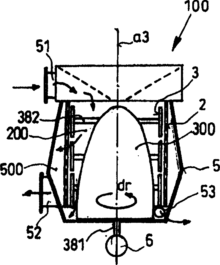
peripheral line of the sieve body. The paddles are fitted to their shafts or the rotor body (300) by screws or rivets and / or an adhesive, solder or welding, especially so that the paddles can be replaced. The tangent plane (etf) at the leading end zone or near the tip or the 
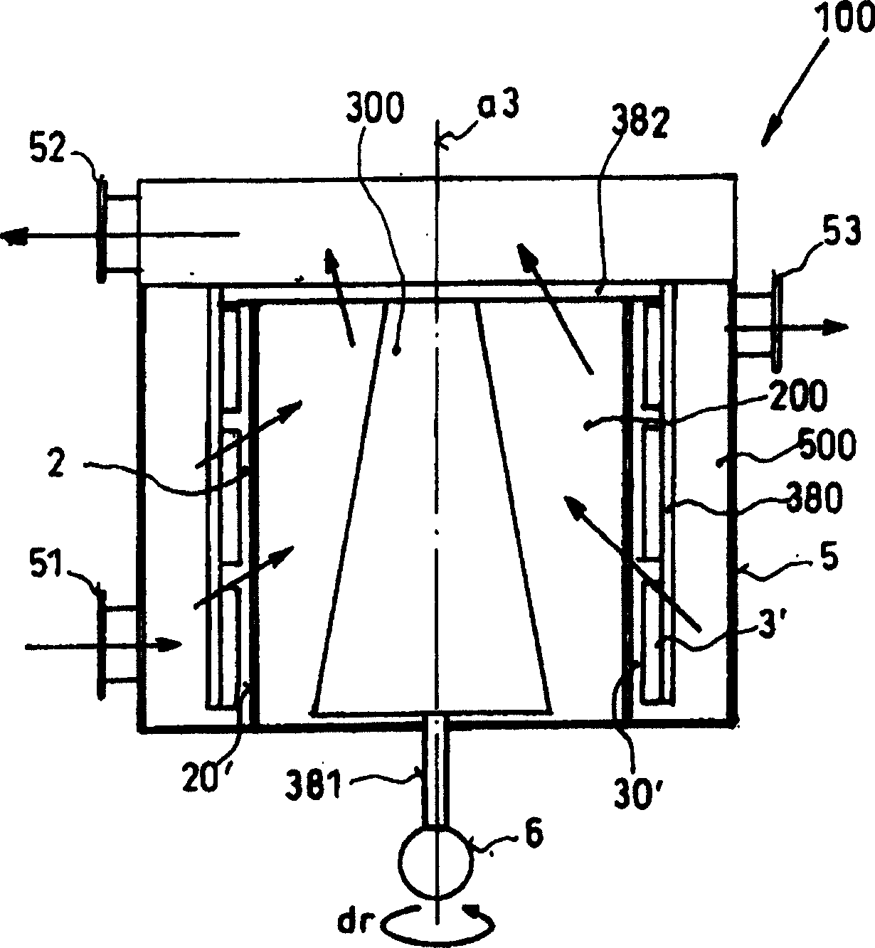
leading edge of the paddle, towards the sieve body, is at an angle ( alpha ) of 0-15 degrees and preferably 0-8 degrees and especially 0-2 degrees with the tangent plane (ets) on the surface of the sieve body towards the paddle at the radial working line (ezs). When the rotor (300) with the paddles is in position, within the sieve body, the paddle surface at right angles to the rotor axis has a curvature which is larger than the curvature of the sieve surface towards the paddles. If the paddles are mounted outside the sieve body, their surface curvature is smaller than the facing outer surface (20') of the sieve body. The paddles have a plate structure, with a constant thickness (ms) from the leading to the trailing ends, preferably of 2-8 mm and especially 5-6 mm. The paddle plates are of curved sheets, with parallel outer and inner surfaces. The paddle surface towards the sieve body has a stronger curvature at the leading zone at the leading tip or edge than in the trailing zones, with a stronger curvature of 5-20% and preferably 10-15% stronger than the curvature of the facing surface of the sieve body. The curvature of the trailing zones of the paddle surface towards the sieve surface is 0-4% stronger than the curvature of the facing sieve surface. The transit between the two curvature structures is at the center one-third of the longitudinal line of the paddle surface, with a steady shift from the stronger to the weaker curve line. The surface of the paddle towards the sieve is parallel to the rotor (300) axis. The end surface of the paddle surface has a narrow rectangle shape, and both leading edge corners (3101, 3102) are rounded. On a plan view, the leading end of the paddle surface, in the direction of rotation, is narrower than the trailing end, in the shape of a triangle, delta, trapezoid or swallowtail. The side edges of the paddle surface are aligned outwards and back from the leading end by an angle of 40-120 degrees and preferably 60-90 degrees . The side edges are straight, curved or stepped. The paddle surface can be fitted with spaced linear projections or recesses, pitched at an angle of 10-45 degrees and especially 15-30 degrees to the working end (esf). The projections are held in place by solder, welding or an adhesive, or recesses are machined out as grooves. The separate paddles at the rotor together form an expanding spiral configuration in the direction of rotation. The rotor (300), fitted with the paddles, forms rotor modules, with the paddles fitted by carrier bars to the shafts from the rotor center. The ratio of the minimum paddle surface / sieve surface gap to the maximum gap (arh) is 0.05-0.5 and preferably 0.1-0.3. An Independent claim is included for paddles with mountings to be fitted to the carrier bars a sleeves, openings, drillings or shoulders, or threaded holes for screw fasteners.

Description

technical field [0001] The present invention relates to a new type of screening machine, which is used for screening materials such as papermaking, board, etc., especially for screening mechanical pulp, chemical pulp, deinked or non-deinked secondary fibers, waste, and used for the purification of pulp and grading, for the treatment of white water, to remove impurities such as wood, stone, metal or plastic particles, ink, resin, etc.; Background technique [0002] Screening equipment for separating unwanted particulate impurities from fibrous material, especially woody material, in the paper, board, etc. industry is known in different structural designs and is widely used in the paper industry all over the world. [0003] Known screening machines have blades mounted on a rotor, the cross-section of the blades in the direction of rotation is similar to that of an aircraft wing, starting with a spherical curve in the direction of rotation, then gradually converging towards the...

Claims


Application Information

Patent Timeline
IPC IPC(8): D21D5/06B07B1/50D21D5/02
CPCD21D5/026
Inventor H·加布尔A·皮希勒A·格歇德尔
Owner ANDRITZ AG
Why Eureka
Try Eureka