Methods and appts. for operating high energy accelerator in low energy mode

An accelerator, low-energy technology, applied in the field of charged particle accelerators, which can solve the problem that ion implantation is not a trivial matter

Inactive Publication Date: 2005-06-29
VARIAN SEMICON EQUIP ASSOC INC
View PDF0 Cites 0 Cited by
  • Summary
  • Abstract
  • Description
  • Claims
  • Application Information

AI Technical Summary

Problems solved by technology

[0006] However, ion implantation with a

Method used


Image

  • Methods and appts. for operating high energy accelerator in low energy mode
  • Methods and appts. for operating high energy accelerator in low energy mode
  • Methods and appts. for operating high energy accelerator in low energy mode

Examples


Embodiment Construction

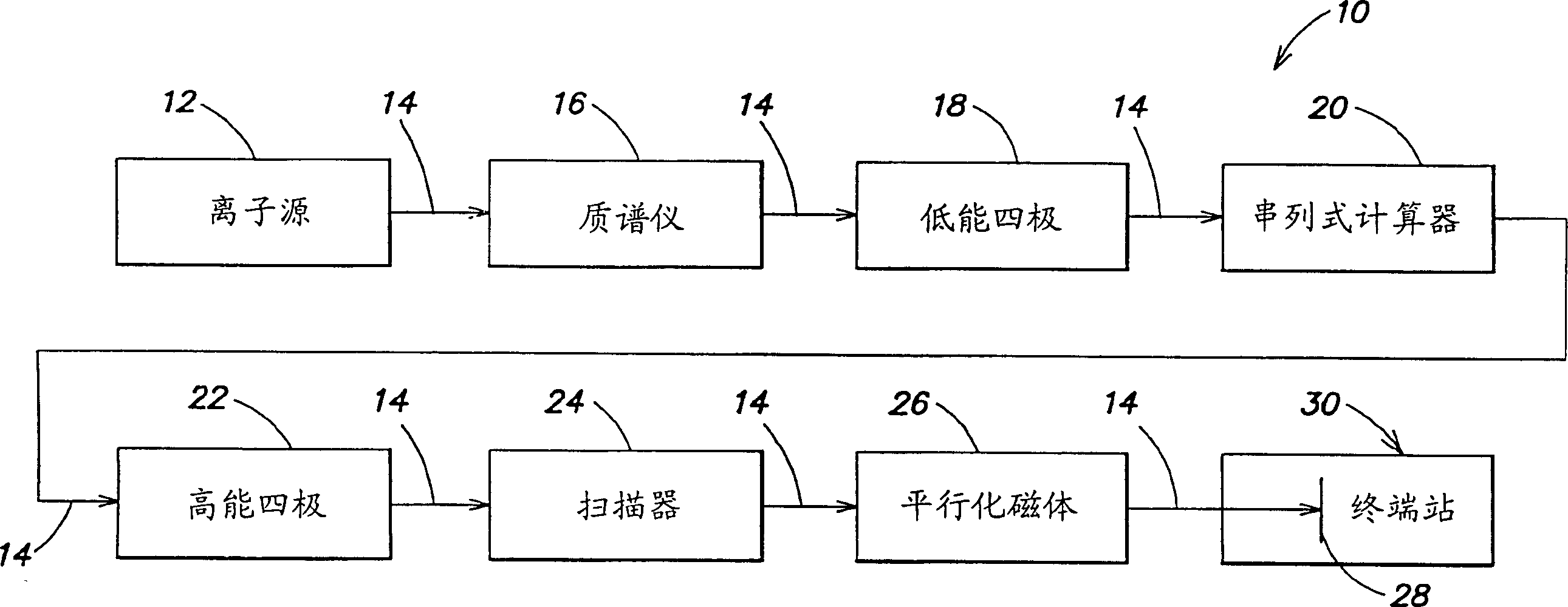
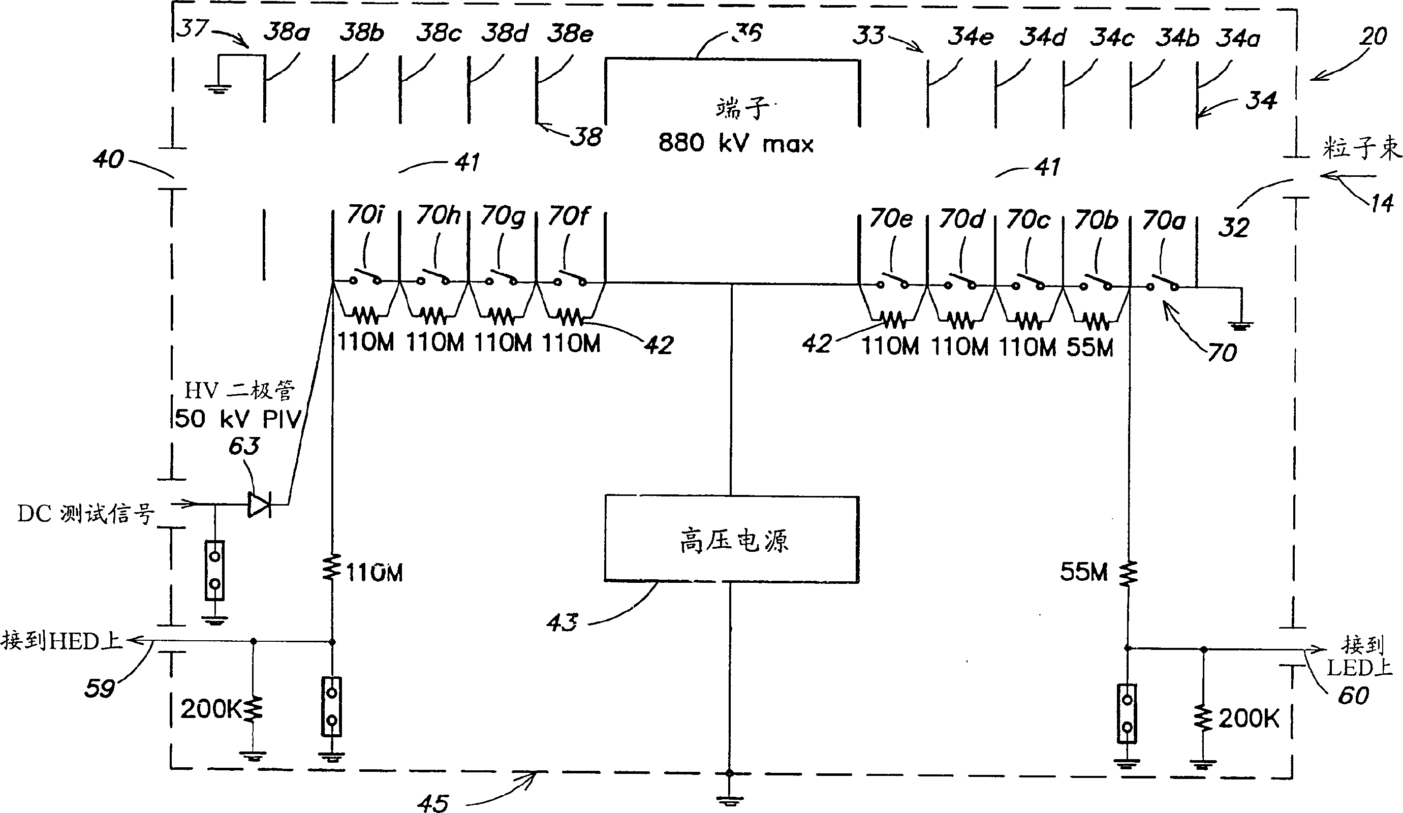
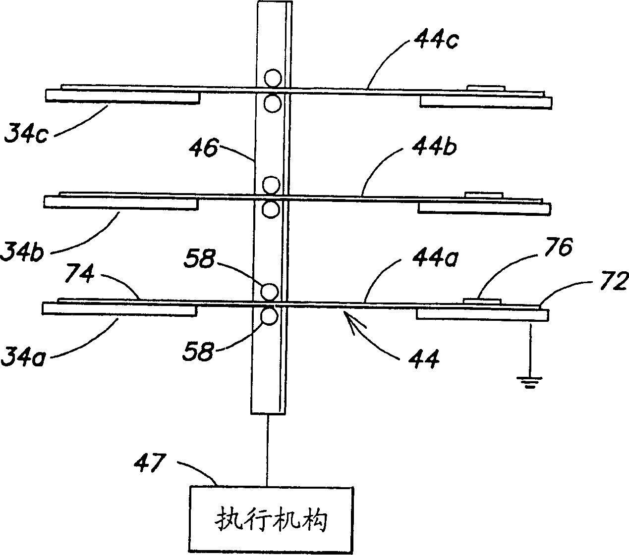
[0034] The ion implantation apparatus according to the invention is capable of operating at high energy in a high energy mode and at low energy in a low energy mode. In one aspect of the invention, efficient low energy operation is achieved in the high energy injection apparatus by providing means and methods for connecting the accelerator electrodes of the high energy accelerator to a reference potential such as ground or a negative voltage in the low energy mode . By tying the accelerator electrodes to a reference potential, the positive potential is removed from the accelerator electrodes, thereby minimizing the likelihood that residual parasitic potentials or charges from particle beam buildup will adversely affect the ion beam during low energy implantation. Specifically, switching assemblies are used to prevent uncontrolled accelerator electrode voltages that would otherwise remove free electrons from the ion beam and reduce directional delivery through the ion implantat...


PUM


Abstract

The invention provides a method and apparatus for efficiently operating an ion implantation apparatus including a charged particle accelerator in high energy mode and low energy mode. A charged particle accelerator includes a high voltage power supply, an accelerator column coupled to the high voltage power supply, and a switch assembly. The accelerator pillar includes a multitude of accelerator electrodes. The high voltage power supply is disabled in low energy mode to energize the accelerator pillars to release energy. The switch assembly includes a switch element that electrically connects the accelerator electrode to the reference potential in the low energy mode and electrically isolates the accelerator electrode from the reference potential in the high energy mode. In the low energy mode, the switch assembly prevents positive potentials on the accelerator electrodes while delivering the positive ion beam, and thus minimizes space charge expansion of the ion beam.

Description

[0001] This patent application claims the benefit of Provisional Patent Application Serial No. 60 / 182,079, filed February 11, 2000, which is hereby incorporated by reference. technical field [0002] This invention relates to charged particle accelerators, and more particularly to methods and apparatus for operating high energy accelerators in a low energy mode. Background technique [0003] Ion implantation is a commercially accepted standard technique for introducing conductivity-altering impurities into semiconductor wafers. In a traditional ion implantation system, the desired impurity material is ionized in the ion source, the ions are accelerated into an ion beam of specified energy, and then the ion beam is aligned on the wafer surface. The energetic ions in the ion beam penetrate most semiconductor materials and become embedded in the crystal lattice of the semiconductor material, creating regions of desired conductivity. [0004] Stringent requirements related to t...

Claims


Application Information

Patent Timeline
IPC IPC(8): H05H5/06H01J37/317H01L21/265H05H5/02
CPCH01J37/3171H01J2237/04735H05H5/06H05H5/02
Inventor 布乔恩·O·派德森彼得·E·马西乔斯基威廉·G·古德诺思保罗·J·墨菲查尔斯·M·麦肯纳
Owner VARIAN SEMICON EQUIP ASSOC INC
Why Eureka
Try Eureka