Micropowder functional material production method

A technology of functional materials and manufacturing methods, applied in the direction of fibrous fillers, chemical instruments and methods, botany equipment and methods, etc., can solve problems such as large time burden, obstacles to rationalization of manufacturing processes, and high product costs

Inactive Publication Date: 2005-07-06
ERUBU
View PDF3 Cites 0 Cited by
  • Summary
  • Abstract
  • Description
  • Claims
  • Application Information

AI Technical Summary

Problems solved by technology

[0007] However, such a process requires a large burden in terms of equipment, labor (workload), time, etc., and as a result, the cost of the product is also high, but it is impossible to omit the necessary steps for processing ceramics, so there are naturally obstacles to the rationalization of the manufacturing process.

Method used


Image

  • Micropowder functional material production method
  • Micropowder functional material production method
  • Micropowder functional material production method

Examples


Embodiment 1~3

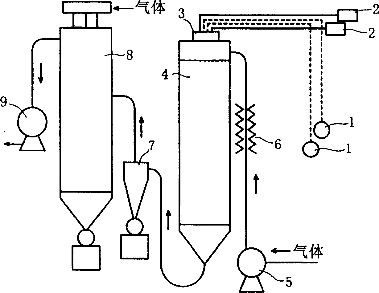
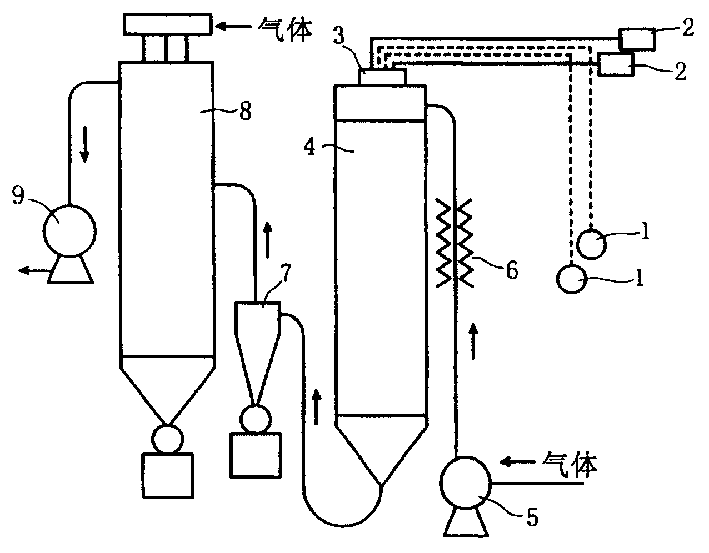
[0071] figure 1 It is an explanatory diagram showing the spray drying apparatus used in the method of the present invention.

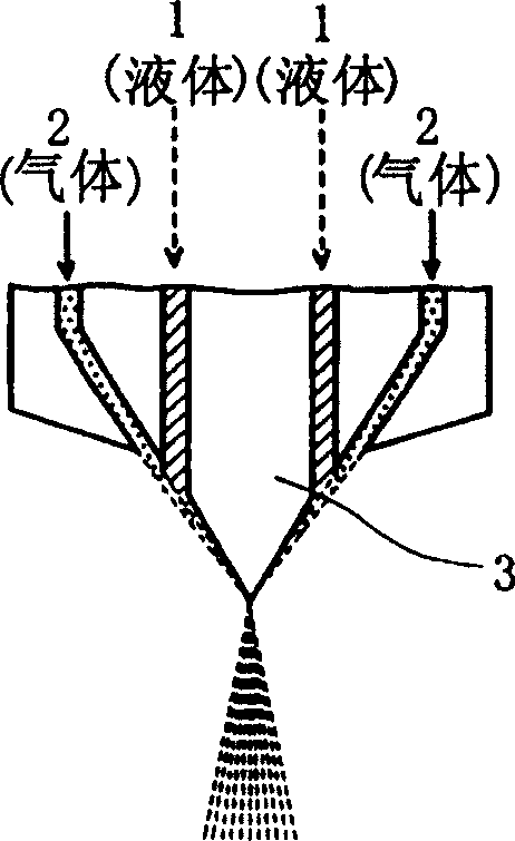
[0072] figure 2 yes figure 1 An enlarged illustration of the four-fluid nozzle in the setup.

[0073] exist figure 1 and figure 2 Among them, 1 is the liquid supply system, 2 is the gas supply system, 3 is the nozzle (four-fluid nozzle), 4 is the device body (tank), 5 is the blower, 6 is the heater, 7 is the cyclone, 8 is the bag filter, 9 is exhaust fan.

[0074] The liquid supply system 1 and the gas supply system 2 are respectively composed of two flow paths, such as figure 2 As shown, spray at the front end of nozzle 3. Recovery (collection) of the product may be performed using both the cyclone 7 and the bag filter 8, or may be performed using either one of them.

[0075] 10 parts by weight of catechin with a purity of 30% by weight was added to 100 parts by weight of a hydrocolloid solution of colloidal silicon dioxide having a solid c...

Embodiment 1   Embodiment 2          Embodiment 3

[0087] Time (min) 5 5 60 120 180

[0088] Inlet temperature (℃) 200 250 250 250 250

[0089] Exhaust temperature (℃) 85 107 99 102 111

[0090] Tower inner pressure (kpa) 0.4 0.5 0.8 0.7 0.6

[0091] Supply air volume (m 3 / min) 1.1 0.85 0.85 0.85 0.87

[0092] 1 gas

[0093] Pressure (MPa) 0.69 0.69 0.69 0.69 0.68

[0094] Flow (NL / min) 80 80 80 80 80

[0095] 2 gas

[0096] Pressure (MPa) 0.69 0.69 0.69 0.69 0.69

[0097] Flow (NL / min) 80 80 80 80 80

[0098] 1 liquid

[0099] Flow (ml / min) 20 20 20 20 10

[0100] 2 liquids

[0101] Flow (ml / min) 20 20 20 20 10

[0102] BF cylinder internal pressure (kPa) 0.3 0.4 1 0.7 0.5

[0103] Recovery (g) 46.8 32.6 94.6 877 722

[0104] Median diameter (μm) 5.614 6.075 5.808 6.412 5.949

[0105] Mode diameter (μm) 6.512 6.514 6.512 7.527 6.512

[0106] Average particle diameter (μm) 5.598 6.298 5.873 6.624 6.217

[0107] Standard Deviation 0.293 0.324 0.302 0.329 0.321

[0108] 25% diameter (μm) 3.680 3.914...

Embodiment 4~5

[0112] 40 parts by weight of an aqueous solution having a concentration of 25% by weight of polyamino acid (polylysine) was added to 100 parts by weight of a colloidal silica hydrocolloid solution having a solid content of 40% by weight, and mixed to prepare an aqueous slurry. This aqueous slurry was spray-dried under the conditions of Example 1 using a research spray drying apparatus "Micromist Driya MDL-050-Type B" of Fujisaki Electric Co., Ltd. Conditions and results are shown in Table 2.

[0113] Table 2


PUM

PropertyMeasurementUnit
particle sizeaaaaaaaaaa
lengthaaaaaaaaaa
particle diameteraaaaaaaaaa

Abstract

An object of the present invention is to provide an industrially advantageous method for producing a functional organic component and a ceramic component complex at one go based on a concept different from conventional ones. The water-based slurry (C) containing the functional organic component (A) and the ceramic component (B) is supplied into the tank of the spray drying device in the state of fine droplets, and hot air is blown into the tank, so that the The liquid droplets are dried and pulverized when they come into contact with hot air in the tank, so that a finely powdered mixture in which the organic component (A) and the ceramic component (B) are mixed is obtained at one go.

Description

technical field [0001] The present invention relates to an industrial method for producing a finely powdered mixed material composed of an organic component having functions such as deodorization and antimicrobial properties and a ceramic component at one go. Background technique [0002] Since the organic components mainly composed of catechins and saponins have functions such as deodorization and antimicrobial properties, fibers and other molded products should be added inside or attached to various materials with appropriate binders when they are formed. On the surface of the object, materials with functions such as deodorization and antimicrobial properties can be obtained. [0003] In this case, since the organic components are easily lost due to the contact of the material with these organic components added or adhered thereto with water, the sustainability is poor. [0004] Therefore, the present applicant made organic components such as catechin and saponin into...

Claims


Application Information

Patent Timeline
Patent Type & Authority Patents(China)
IPC IPC(8): A61L9/01A01N25/08A61L9/16B01D1/18C09C1/30C09C3/04
CPCC01P2004/61C09C1/3027C09C1/3063C09C1/3072C09C1/309C09C3/043
Inventor 佐野昌隆宫松宏树吉田贵美后藤宣夫
Owner ERUBU
Why Eureka
Try Eureka