Method for manufacturing uranium foils containing fine crystals

A crystal and melt technology, applied in the field of manufacturing uranium foil containing fine crystals, can solve problems such as destruction and deformation of uranium foil

Inactive Publication Date: 2005-08-03
KOREA HYDRO & NUCLEAR POWER CO LTD
View PDF0 Cites 0 Cited by
  • Summary
  • Abstract
  • Description
  • Claims
  • Application Information

AI Technical Summary

Problems solved by technology

[0004] At the same time, uranium foils with excessive residual stress resulting from hot rolling can be deformed or destroyed by thermal cycling and radiation

Method used


Image

  • Method for manufacturing uranium foils containing fine crystals
  • Method for manufacturing uranium foils containing fine crystals

Examples


Embodiment 1

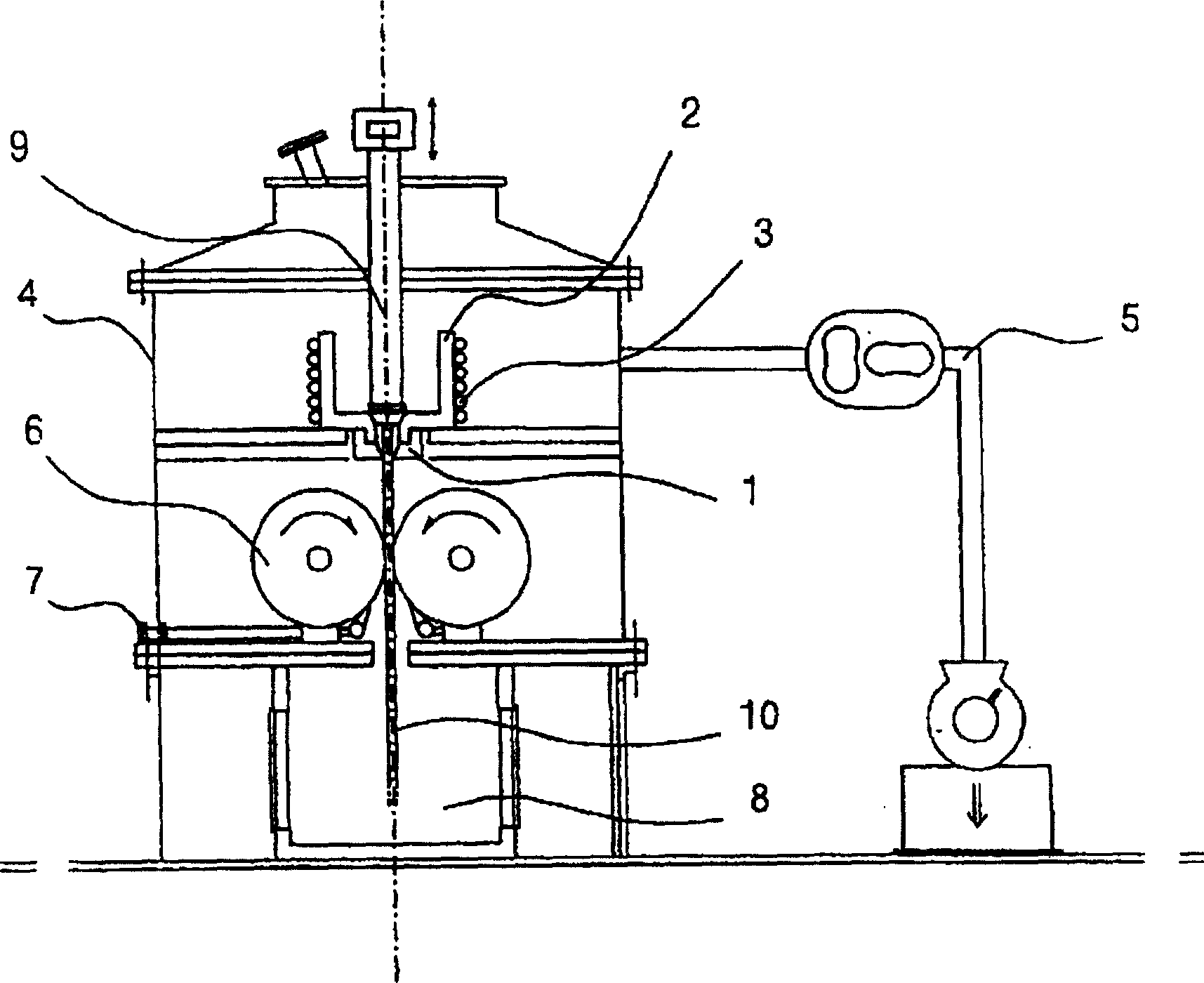
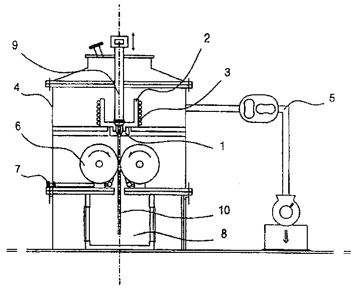
[0027] To manufacture low- or high-enriched uranium foils, uranium material is charged into a refractory crucible (2) with slots (1). The crucible (2) and insulating material (not shown) are assembled in the manufacturing apparatus in proper order.

[0028] Then, the steel chamber equipped with crucible (2) in the device is evacuated to 10 by vacuum pump system (5). -3 tor or higher.

[0029] The high frequency generator (3) is operated to superheat the contents of the crucible to about 200°C above the melting temperature of uranium.

[0030] When the rotation speed of the roller (6) driven by the electric motor is stabilized at about 300 rpm, the plug (9) placed in the crucible (2) is lifted up to discharge the alloy melt.

[0031] The outgoing alloy melt passes through a 1 mm wide slot (1) and then enters the middle of preheated side baffles (not shown) and a roll (6) rotating at about 300 rpm to form a thin foil (10).

[0032] Then, the air inlet valve (7) is operated to...

Embodiment 2

[0037] The invention is applied to low or highly enriched uranium [U-(A)Q-(B)X-(C)Y (Q: Al, Fe, Ni, Si, Cr, Zr elements, X: Al , Fe, Ni, Si, Cr, Zr elements, Y: Al, Fe, Ni, Si, Cr, Zr elements, Q≠X≠Y, (A)≤1% (weight), (B)≤1% ( weight), (C)≤1% (weight))] foil of uranium alloy.

[0038] In order to manufacture U-500ppm Fe-1200ppm Al-500ppm Ni alloy foil, uranium and doping elements including Fe, Al and Ni are appropriately weighed and packed in the crucible according to the required alloy composition. The steel chamber (4) was evacuated to 10 using the vacuum pump system (5) described in the process of making uranium foil. -3 tor or higher.

[0039] Likewise, when the crucible (2) and insulating material (not shown) are installed in the apparatus in proper sequence, the high frequency generator (3) is operated to superheat the contents of the crucible to a temperature higher than that of uranium alloy The melting temperature is about 200°C higher.

[0040] When the rotation ...


PUM


Abstract

The present invention relates to a process producing low or high enrichment uranium and uranium alloy foil, and the fabrication apparatus therefor. Uranium (U) and uranium alloy foil are directly obtained from a melt, not through a vacuum induction melting and casting, ingot cutting, hot-rolling and heat-treatment process, but through melt spinning or a twin-roll casting process. Major advantages have been obtained as follows: 1) a simplified process without the hot-rolling process and heat-treatment process, 2) an improvement in productivity and process economics in foil fabrication, and 3) a high purity and a high quality of the foil.

Description

technical field [0001] The present invention mainly relates to a manufacturing method and a manufacturing apparatus for rapid solidification of uranium foil containing fine crystal grains from a melt using cooling rolls. In more detail, the present invention relates to low- or highly-enriched uranium and uranium alloy foils, their manufacturing apparatus and manufacturing method, wherein uranium (U) and uranium alloy [U-(A)Q-(B)X-(C)Y (Q: Al, Fe, Ni, Si, Cr, Zr elements, X: Al, Fe, Ni, Si, Cr, Zr elements, Y: Al, Fe, Ni, Si, Cr, Zr elements, Q≠X≠ Y, (A) ≤ 1% (weight), (B) ≤ 1% (weight), (C) ≤ 1% (weight))] foil is obtained by direct casting from the melt, without vacuum induction melting and casting , ingot cutting, hot rolling and heat treatment processing, but by twin-roll casting processing. Background technique [0002] In general, the conventional manufacturing method of uranium foil has the following unfavorably complex processes: casting the uranium or uranium alloy...

Claims


Application Information

Patent Timeline
IPC IPC(8): G21C23/00B21B1/00B22D11/00B22D11/06C22C1/02C22C28/00C22C43/00G21G4/08
CPCC22C43/00B22D11/0622B22D11/0697B21B1/00
Inventor 金昌圭金淇焕吴石镇张世正金应秀
Owner KOREA HYDRO & NUCLEAR POWER CO LTD
Why Eureka
Try Eureka