
Ultrathin optical panel and a method of making an ultrathin optical panel

An optical and panel technology, applied in the field of flat optical displays, can solve the problem of increasing the total size of the panel, and achieve the effect of improving contrast and small depth

Inactive Publication Date: 2005-08-17
BROOKHAVEN SCI ASSOCS
View PDF0 Cites 0 Cited by
  • Summary
  • Abstract
  • Description
  • Claims
  • Application Information

AI Technical Summary

Problems solved by technology

Such panels can be thinner than their width and height, and the cladding of the waveguide can be made black to increase the black surface area, but such panels may require expensive and complex projection equipment to be used throughout the narrow distributing imaging light on the entrance face, the device enables an increase in the overall size of the panel

Method used


Image

  • Ultrathin optical panel and a method of making an ultrathin optical panel
  • Ultrathin optical panel and a method of making an ultrathin optical panel
  • Ultrathin optical panel and a method of making an ultrathin optical panel

Examples


Embodiment Construction

[0027] It should be understood that these drawings and descriptions of the present invention have been simplified to illustrate the relevant elements necessary for a clear understanding of the present invention, while leaving out for the sake of clarity many other elements encountered in a typical optical display panel . Those of ordinary skill in the art will appreciate that other such elements are desirable and / or required in order to practice the present invention. However, since such elements are well known in the art, and because they do not contribute to a better understanding of the invention, a discussion of these elements is not provided here.

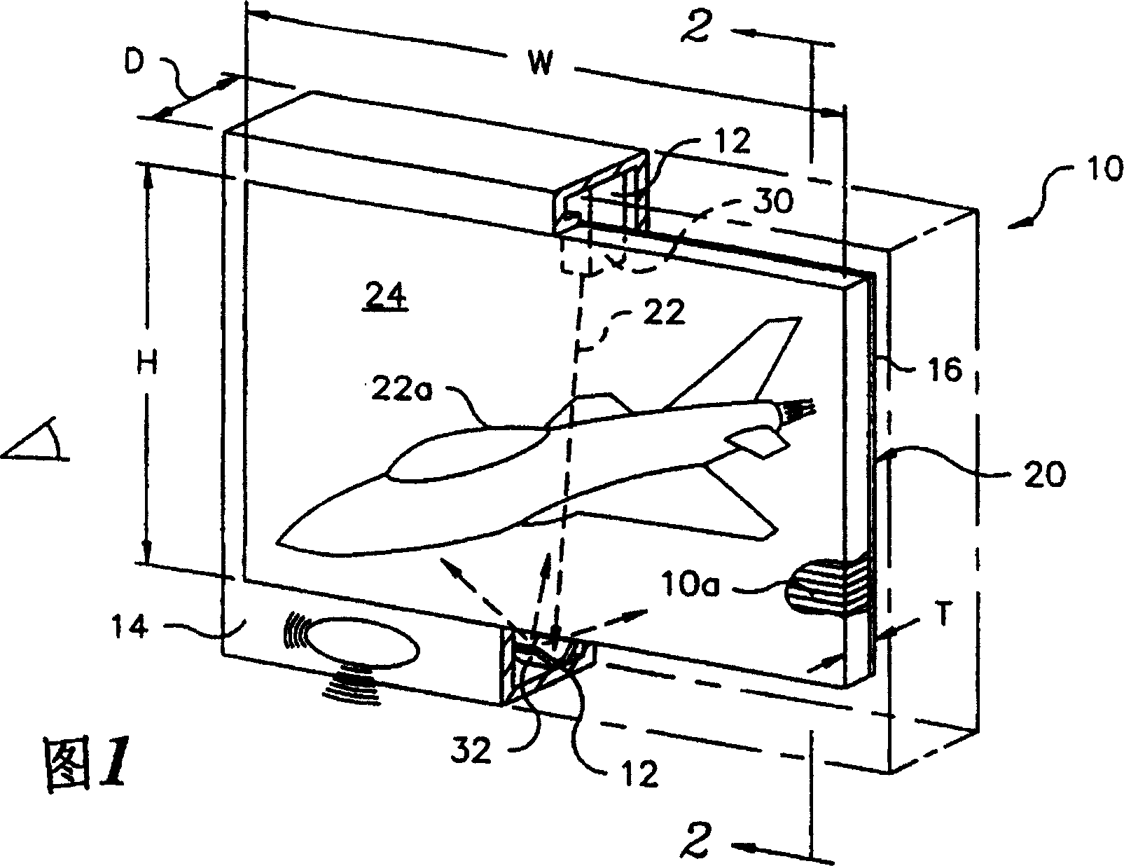
[0028] FIG. 1 is a schematic isometric view illustrating an optical panel 10 . The optical panel 10 includes a plurality of waveguides 10a, wherein one end of each waveguide 10a forms the entrance of the waveguide, the opposite end of each waveguide 10a forms the exit of the waveguide 10a, a light emitting system 12, and a ho...


PUM


Abstract

An ultrathin optical panel, and a method of producing an ultrathin optical panel, are disclosed, including stacking a plurality of glass sheets, which sheets may be coated with a transparent cladding substance or may be uncoated, fastening together the plurality of stacked coated glass sheets using an epoxy or ultraviolet adhesive, applying uniform pressure to the stack, curing the stack, sawing the stack to form an inlet face on a side of the stack and an outlet face on an opposed side of the stack, bonding a coupler to the inlet face of the stack, and fastening the stack, having the coupler bonded thereto, within a rectangular housing having an open front which is aligned with the outlet face, the rectangular housing having therein a light generator which is optically aligned with the coupler. The light generator is preferably placed parallel to and proximate with the inlet face, thereby allowing for a reduction in the depth of the housing.

Description

[0001] Cross References to Related Applications [0002] This application is a continuation-in-part of US Patent Application Serial No. 09 / 145,411, filed 8 / 31 / 98, entitled "Ultrathin Diaplay Panel." [0003] Statement Regarding Federally Sponsored Research and Development [0004] This invention was made with Government support under Contract No. DE-AC02-98CH10886 with the US Department of Energy. The government has certain rights in this invention. technical field [0005] The present invention relates to a flat optical display, more precisely, to an ultra-thin display panel and a method for manufacturing the ultra-thin display panel. Background technique [0006] Optical screens typically use cathode ray tubes (CRTs) to project images onto the screen. A standard screen has a 4:3 aspect ratio and a vertical resolution of 525 lines. The beam of electrons is scanned horizontally and vertically across the screen, creating a large number of pixels that are combined to form ...

Claims


Application Information

Patent Timeline
Patent Type & Authority Patents(China)
IPC IPC(8): G02B27/18G02B6/06G02B6/08G03B21/00H04N5/74H04N9/31
CPCG02B6/08H04N9/3102H04N9/3141H04N5/7416Y10S385/901H04N9/3129G02B6/06G02B6/04
Inventor 克鲁斯·比斯卡蒂卡尔文·布鲁斯特莱昂纳德·德桑托詹姆斯·T·沃利丹
Owner BROOKHAVEN SCI ASSOCS
Features
  • Generate Ideas
  • Intellectual Property
  • Life Sciences
  • Materials
  • Tech Scout
  • Unparalleled Data Quality
  • Higher Quality Content
  • 60% Fewer Hallucinations
Learn More