Method and apparatus for injection molding of semisolid alloys

A molding method and semi-solid technology, applied in the field of semi-solid alloy injection molding and equipment, can solve the problems of semi-solid slurry leakage, increased processing cost, erosion damage, etc. The effect of simplifying the process

Inactive Publication Date: 2005-08-24
刘伟杰
View PDF10 Cites 2 Cited by
  • Summary
  • Abstract
  • Description
  • Claims
  • Application Information

AI Technical Summary

Problems solved by technology

At the same time, the workability of these alloy materials is very poor (US Patent No. 5996679), resulting in increased processing costs
Regular replacement of the rotating screw due to wear also increases the maintenance cost of the equipment
All of this means that the use of rotating screws and fully heated slurry sleeves is a major contributor to the high manufacturing and maintenance costs of conventional injection molding machines
[0006] 2. The use of rotary screw not only increases the cost of equipment manufacturing and maintenance, but also causes process problems such as semi-solid slurry back leakage
US Patent No. 6474399 pointed out that under the action of high injection pressure, the semi-solid slurry can leak back to the screw sleeve and even the driving mechanism of the screw through the gap between the inner wall of the sleeve and the rotating screw, causing erosion damage
[0007] 3. The slurry sleeve must be opened and cleaned when changing the type of alloy
However, if the stirring is insufficient, the dendrites in the scraps are too complete, or the solid phase content in the slurry is too high, the original dendrites may degenerate incompletely

Method used


Image

  • Method and apparatus for injection molding of semisolid alloys
  • Method and apparatus for injection molding of semisolid alloys
  • Method and apparatus for injection molding of semisolid alloys

Examples


Embodiment Construction

[0034] The main difference between the injection molding method provided by the present invention and existing methods is that it does not require the use of conventional rotating screws or pistons. In this way, equipment manufacturing and operating costs can be significantly reduced while retaining most of the characteristics of traditional injection molding machines.

[0035] The method is realized through the following steps: a non-dendritic raw material rod is fed into a slurry sleeve, and a given length section of the head of the non-dendritic raw material rod is heated to a point between its solidus line and liquidus line. A certain temperature generates a semi-solid slurry, and the solid part of the non-dendritic raw material rod is used as a disposable piston to inject the semi-solid slurry in front of it into the mold cavity.

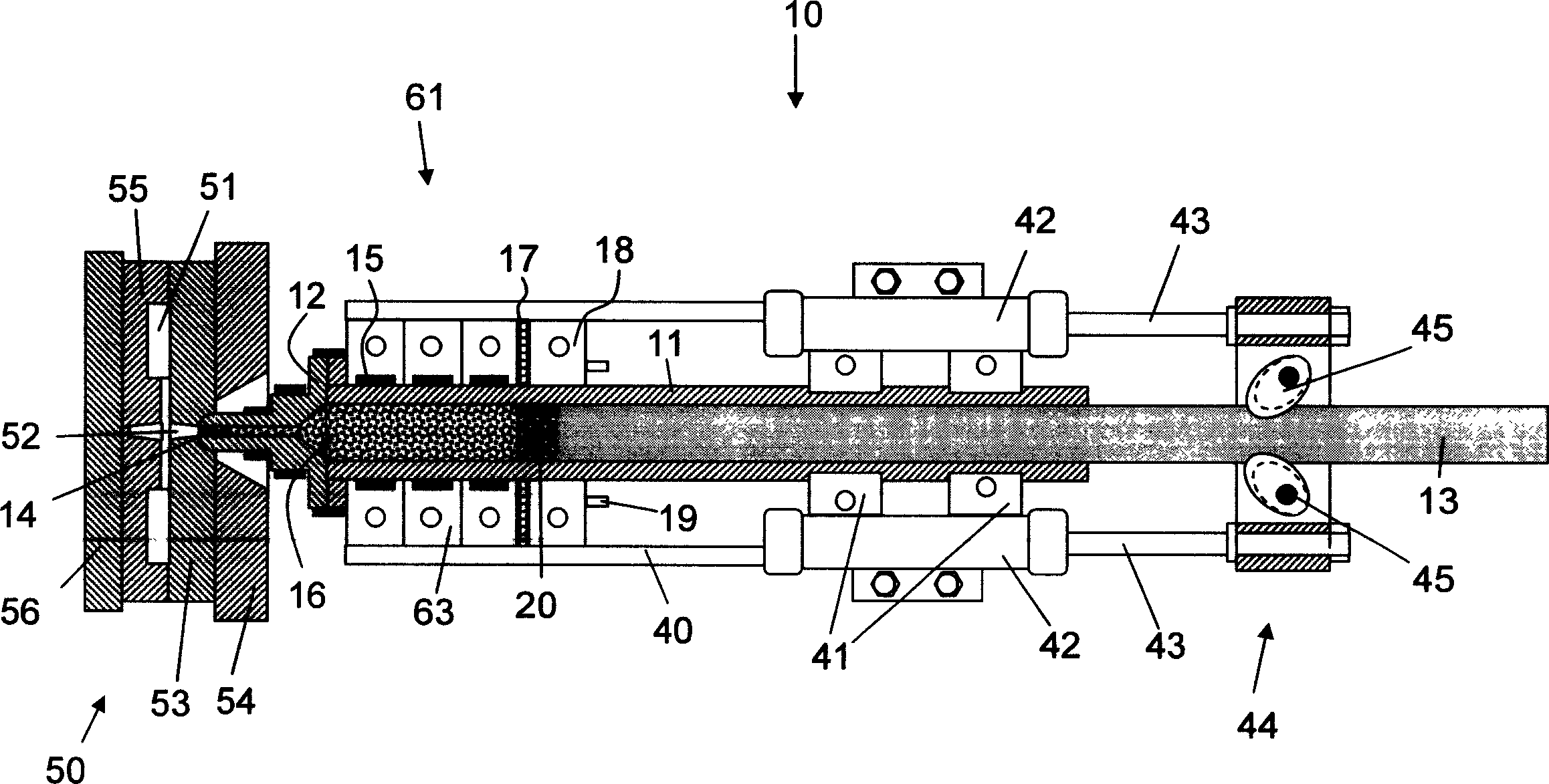
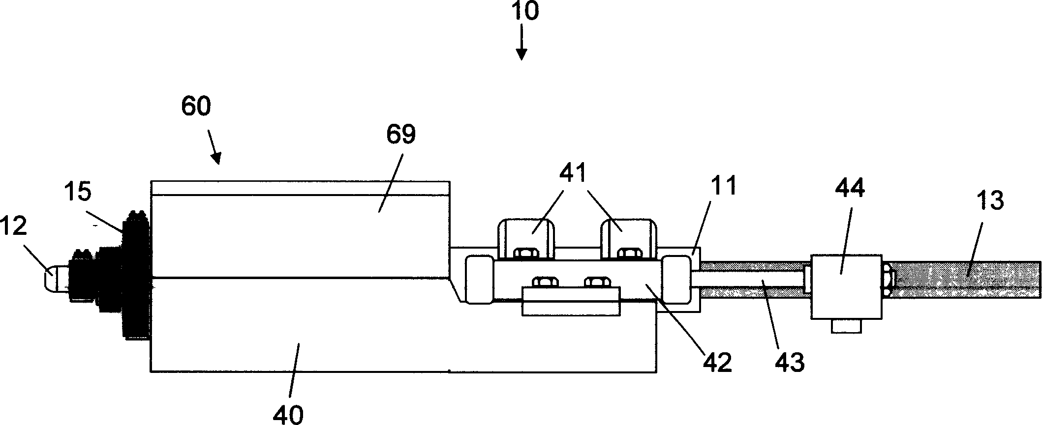
[0036] The above steps can be used as figure 1Shown injection molding machine (10) to complete. The injection molding machine (10) comprises...


PUM


Abstract

A method and apparatus for thixotropic molding of semisolid alloys are disclosed. The method comprises of feeding a dendritic-free feedstock bar into an extruder barrel, melting a terminal portion of the feedstock bar into a semisolid slurry by heating it to a temperature between its solidus and liquidus temperatures, and using the solid portion of the feedstock bar as an one-time 'plunger' to inject the semisolid slurry into a mold cavity. The apparatus based on the present method, which is equipped without a regular extruder screw or plunger, uses a feedstock bar as a one-time plunger to inject semisolid slurries formed from a terminal portion of the same feedstock bar.

Description

technical field [0001] The invention relates to a semi-solid metal material injection molding method and equipment, which is characterized in that a non-dendritic raw material rod is used to transform the semi-solid slurry formed by its own head without using a conventional rotating screw or piston The material is injected into the mold cavity. Background technique [0002] Injection molding is a new metal forming technology; the process is to convert the alloy raw material into a semi-solid slurry with spherical metal particles dispersed in the continuous liquid phase metal, and then inject the semi-solid slurry into the mold cavity. Compared with the traditional high-pressure die-casting process, injection-molded parts have the following advantages: 1) no porosity, because the semi-solid slurry has non-Newtonian viscosity (ie, viscosity is inversely proportional to the shear rate); 2) shrinkage is small , because the semi-solid slurry contains solid phase components and ...

Claims


Application Information

Patent Timeline
Patent Type & Authority Patents(China)
IPC IPC(8): B22D17/00B22D23/06
CPCB22D17/007B22D17/2281
Inventor 刘伟杰
Owner 刘伟杰
Why Eureka
Try Eureka