Heat exchange assembly for looped heat pipe

A heat exchange device and heat pipe technology, applied in indirect heat exchangers, lighting and heating equipment, etc., can solve problems such as inconsistency in economy, reduced temperature uniformity, reduced heat transfer, etc., to achieve good heat transfer, manufacturing Low cost, low cost effect

Inactive Publication Date: 2005-09-21
李嘉豪
View PDF0 Cites 3 Cited by
  • Summary
  • Abstract
  • Description
  • Claims
  • Application Information

AI Technical Summary

Problems solved by technology

Since the circuit of this heat pipe heat exchange component is set in the same pipeline, the flow directions of the steam flow and the liquid will conflict with each other in the pipeline, thereby reducing the heat transfer and the residual non-condensable gas in the pipeline will accumulate. At the condensing end, a region with a large temperature difference is formed, thereby reducing the temperature uniformity, and the heat transfer performance is also greatly reduced. Therefore, traditionally, strict requirements are imposed on the manufacturing conditions and storage of the heat pipe, which greatly increases the cost and price. not economical

Method used


Image

  • Heat exchange assembly for looped heat pipe
  • Heat exchange assembly for looped heat pipe
  • Heat exchange assembly for looped heat pipe

Examples


Embodiment Construction

[0026] The present invention will be further elaborated below in conjunction with the accompanying drawings.

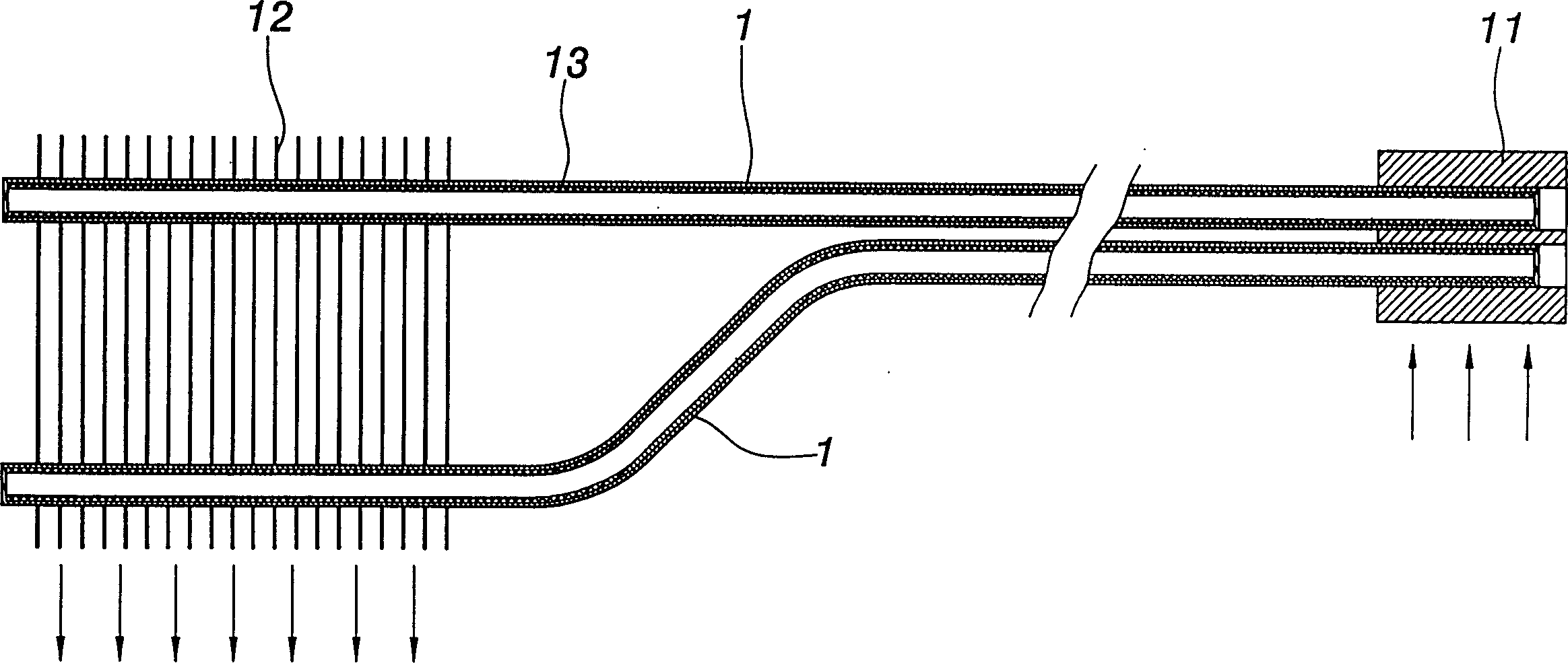
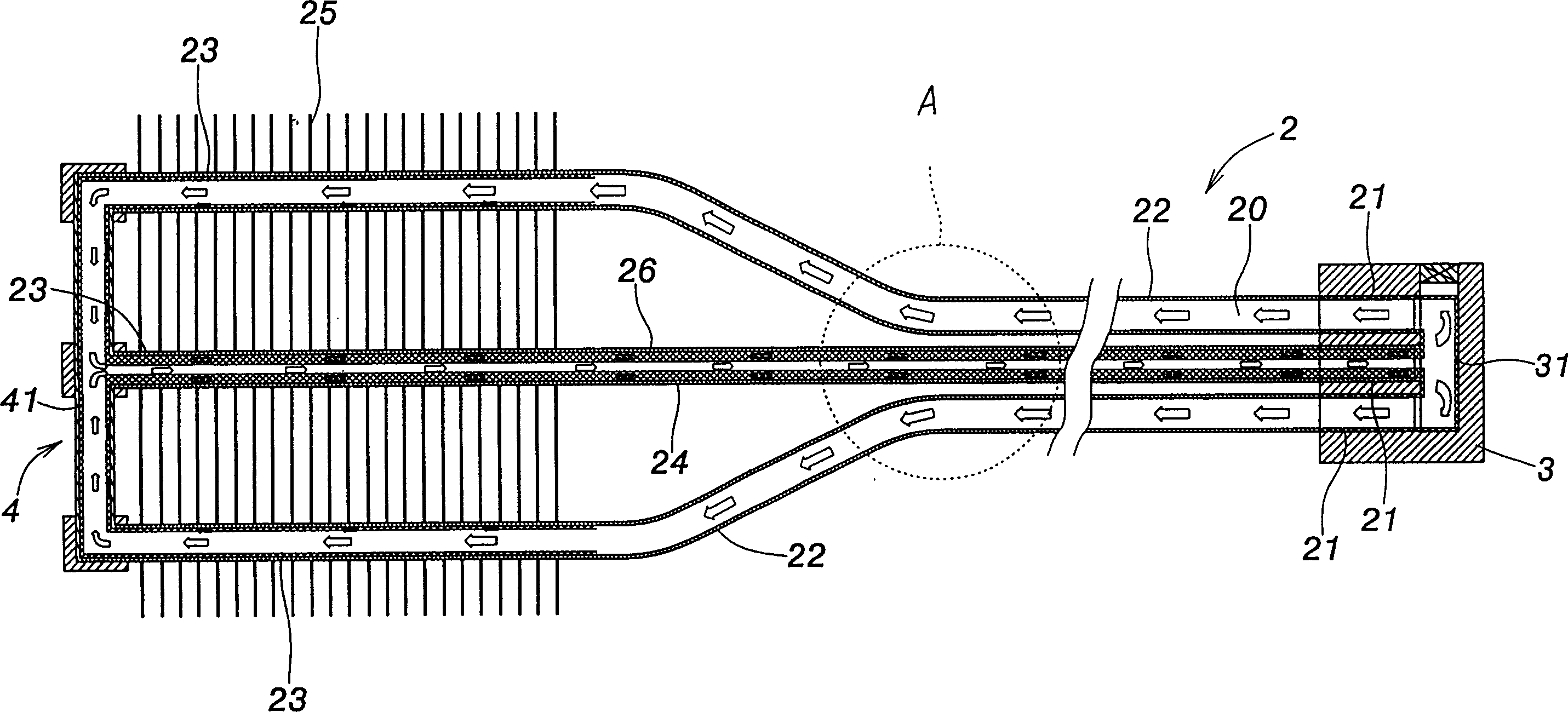
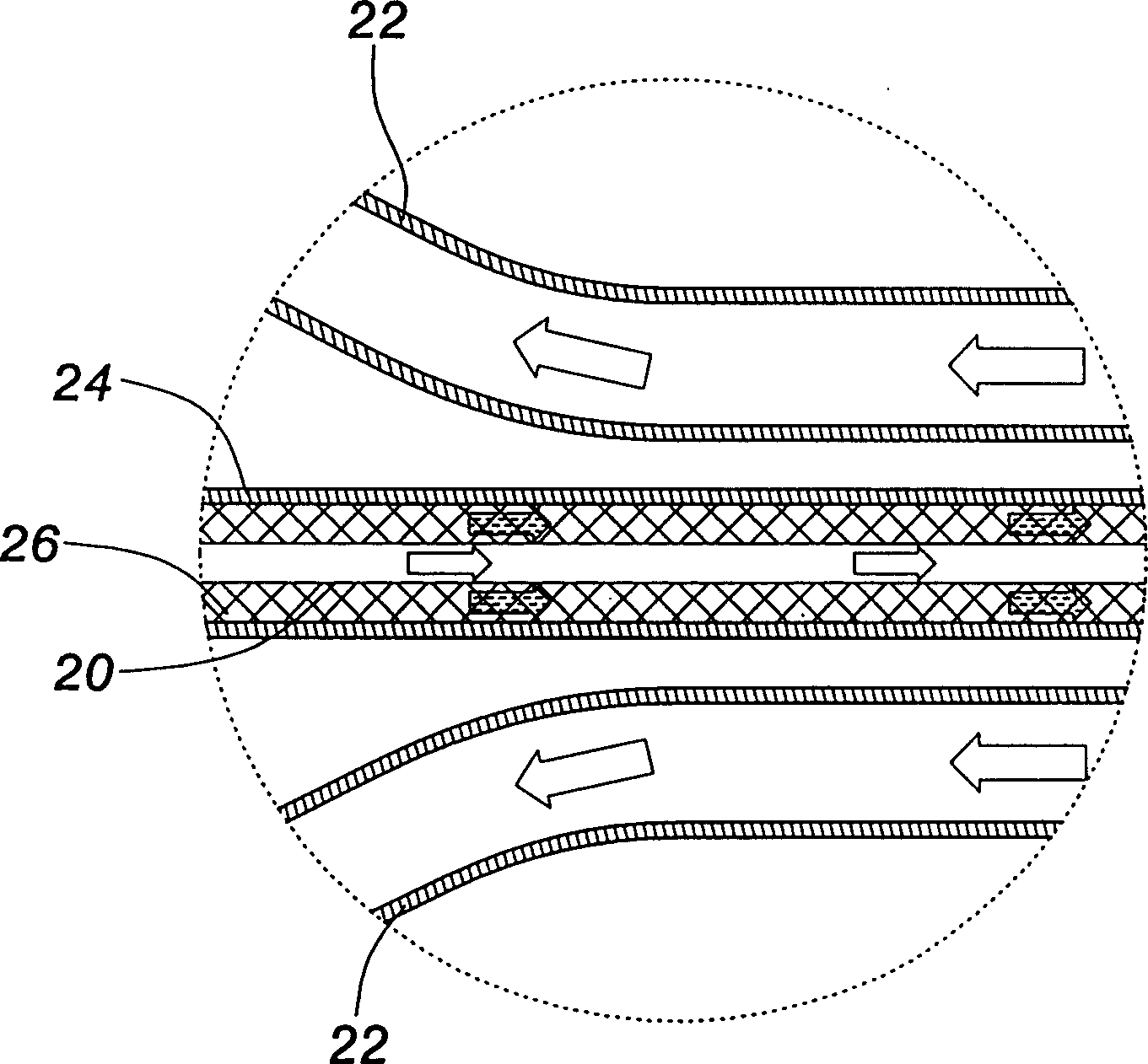
[0027] Such as figure 2 , image 3 , Figure 4 As shown, the present invention includes a closed circuit 2 , an evaporation part 21 , a steam channel 22 , a condensation part 23 , a fluid return channel 24 , a heat transfer block 3 and a connection block 4 connected in series on the closed circuit 2 in sequence.

[0028] An appropriate amount of liquid is filled in the closed circuit 2, and the filling amount of the liquid refers to the volume from filling the capillary tissue to filling the circuit to 90%.

[0029] The fluid return channel 24 and the steam channel 22 are not shared pipelines, that is, the steam channel 22 and the fluid return channel 24 are independent pipelines.

[0030] The flow resistance of the fluid in the fluid return channel 24 is greater than the flow resistance of the fluid in the steam channel 22, resulting in an unbalanced heat flow in...


PUM


Abstract

A circulating-loop hot-tube heat exchange unit has a loop filled with liquid and composed in sequence of serial evaporating part, steam channel, condensing part and fluid return channel. The flowing resistance of fluid in the fluid return channel is higher than that in the steam channel. Its advantages are high heat conductivity, low cost, and long service life.

Description

technical field [0001] The invention belongs to radiator components, in particular to a loop type heat pipe heat exchange assembly. Background technique [0002] The known heat pipe heat exchanging assembly has been widely used in the heat dissipation assembly of electronic components due to its good heat transfer performance. The heat pipe type cooling assembly includes a heat pipe 1 and a heat conduction block 11 connected to the heat pipe 1 and arranged at the end of the electronic component. The other end of the heat pipe 1 is connected to the radiator through another heat conducting block. can also be like figure 1 As shown, the other end of the heat pipe 1 is directly interposed with a heat dissipation fin type heat pipe with several fins 12 . [0003] In the heat pipe manufacturing process, a relatively high part of the cost is used for the cleaning and degassing steps of the pipeline, that is, in the manufacturing steps of pipeline cleaning and vacuuming, the high...

Claims


Application Information

Patent Timeline
Patent Type & Authority Patents(China)
IPC IPC(8): F28D15/04
CPCF28D15/043
Inventor 李嘉豪
Owner 李嘉豪
Why Eureka
Try Eureka