Built-in multi-stage jet pipe type fin heat exchange pipe and manufacturing process thereof

A jet tube and finned tube technology, applied in the field of built-in multi-stage jet tube finned heat exchange tubes and its manufacturing process, can solve the problem that large and medium-sized heat exchangers cannot be used for waste heat recovery, and no heat exchange enhancement measures have been taken , unable to greatly improve the comprehensive heat transfer coefficient, etc., to achieve the effect of increasing heat transfer, improving heat transfer efficiency, and expanding heat transfer area

Active Publication Date: 2015-07-29
NANJING SHENGNUO HEAT PIPE
View PDF7 Cites 3 Cited by
  • Summary
  • Abstract
  • Description
  • Claims
  • Application Information

AI Technical Summary

Problems solved by technology

[0022] The patent application number is 201110003743.0 "Heat Exchange Tube for Evaporator and Evaporator Composed of It" is used in the evaporator of refrigeration equipment, no measures are taken to enhance heat exchange outside the tube, and the comprehensive heat transfer coefficient cannot be greatly improved, so it cannot Large and medium heat exchangers used in industrial production for waste heat recovery

Method used


Image

  • Built-in multi-stage jet pipe type fin heat exchange pipe and manufacturing process thereof
  • Built-in multi-stage jet pipe type fin heat exchange pipe and manufacturing process thereof

Examples


Embodiment Construction

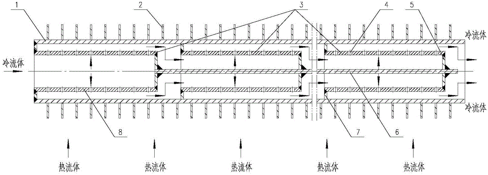
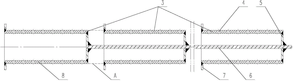
[0043] like figure 1 , 2 As shown, the built-in multi-stage jet tube finned heat exchange tube provided by the present invention includes a fin tube 1, and a multi-stage jet tube 3 is installed inside the fin tube, and the multi-stage jet tube 3 includes at least Two coaxial sub-level jet tubes connected in series; one end of each sub-level jet tube is open, and an annular cover 7 is welded on the outer wall at the open end, and a bottom cover with a central hole is welded at the other end 5. The open ends of the jet tubes of each sub-level are in the same direction, which is opposite to the flow direction of the cold fluid; put the tie rod 6 through the center hole of the bottom cover 5 of the jet tubes of each sub-level to ensure that the gap between the jet tubes of two adjacent sub-levels A certain distance is left, and then the tie rod 6 is welded step by step with the bottom cover 5 of each sub-stage jet tube, and connected in series to form a multi-stage jet tube 3 . Sp...


PUM

PropertyMeasurementUnit
distanceaaaaaaaaaa
thicknessaaaaaaaaaa

Abstract

The invention provides a built-in multi-stage jet pipe type fin heat exchange pipe. The built-in multi-stage jet pipe type fin heat exchange pipe comprises a fin pipe, and a multi-stage jet pipe mounted in the fin pipe, wherein the multi-stage jet pipe comprises at least two second-stage jet pipes which are coaxially connected in series; an opening is formed in one end of each second-stage jet pipe, and an annular sealing cover is welded on the outer wall of the opening end; a bottom cover is welded at the other end of each second-stage jet pipe; the opening ends of the second-stage jet pipes are toward the same direction and in the direction opposite to the cold liquid flowing direction; a certain of space is set between every two adjacent second-stage jet pipes, and the every two adjacent second-stage jet pipes are fixedly connected in series through a pulling rod to form the multi-stage jet pipe; a spraying hole is formed in the wall of each second-stage jet pipe. According to the built-in multi-stage jet pipe type fin heat exchange pipe, the convection heat exchange in the pipe is enhanced through the multi-stage jet pipe; the heat transfer is enhanced at the outside of the pipe by a manner of increasing the heat exchange area through welding fins; therefore, the total heat exchange efficiency can be obviously increased; the heat exchange pipes can be connected in parallel and flexibly designed to be large, medium and small-size heat exchangers according to the demand of the production process.

Description

technical field [0001] The invention relates to heat exchange equipment in various fields such as chemical industry, metallurgy, energy saving and environmental protection, and in particular to a built-in multi-stage jet tube fin heat exchange tube and its manufacturing process. Background technique [0002] With the rapid development of modern industry, countries all over the world are generally facing the problem of energy shortage. The development of new energy and how to efficiently use existing energy have received widespread attention from all countries in the world. Due to the wide application of heat exchange equipment in industrial production, improving the efficiency of heat exchangers and researching new technologies to enhance heat exchange have become a new topic of heat transfer that people are paying more and more attention to. The application of enhanced heat transfer technology not only saves energy and protects the environment, but also saves investment and...

Claims


Application Information

Patent Timeline
Patent Type & Authority Applications(China)
IPC IPC(8): F28F1/42B23P15/26
Inventor 郭宏新詹岳陈兴元杨峻
Owner NANJING SHENGNUO HEAT PIPE
Why Eureka
Try Eureka