Dry-type hot water heating floor

A hot water and dry technology, applied to floors, building components, buildings, etc., can solve the problems of large downward heat transfer ratio, small floor area heat dissipation, small heating pipe diameter, etc., to achieve small temperature changes, Effect of increasing heat transfer and reducing thickness

Inactive Publication Date: 2011-08-17
北京建筑工程学院
View PDF0 Cites 3 Cited by
  • Summary
  • Abstract
  • Description
  • Claims
  • Application Information

AI Technical Summary

Problems solved by technology

However, the diameter of the heating pipe is small, the water quality requirement is high, and the pipe is easy to be blocked; the system resistance is large and the energy consumption is large; the aluminum foil layer is placed on the heating pipe, so that the proportion of heat transfer from the floor to the floor is large, and the heat dissipation per unit floor area of ​​the heating room is small. , not suitable for buildings with poor thermal insulation of the envelope structure and larger units
Although floor heating technology has the advantages of energy saving and comfort, there are still many deficiencies in technology and construction technology, which need to be improved.

Method used


Image

  • Dry-type hot water heating floor
  • Dry-type hot water heating floor
  • Dry-type hot water heating floor

Examples


Embodiment 1

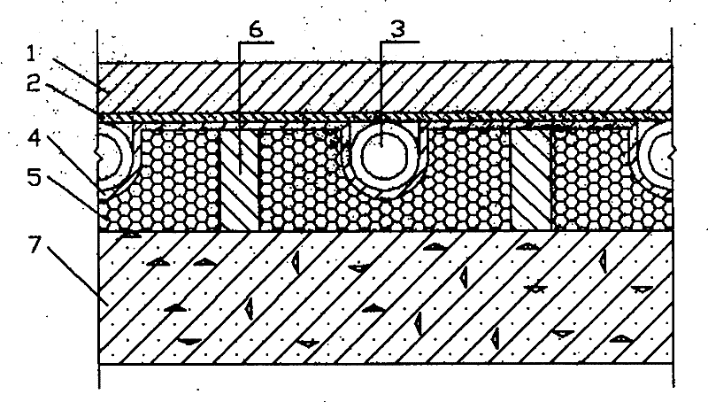
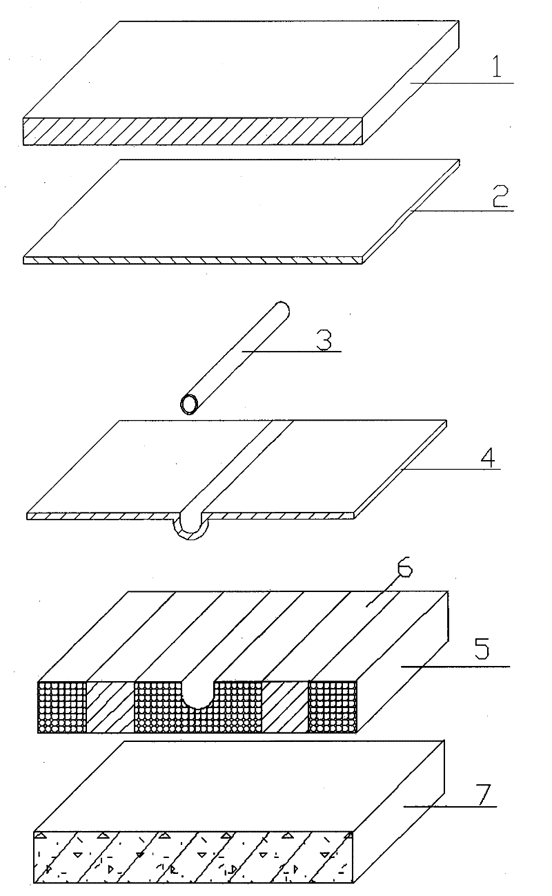
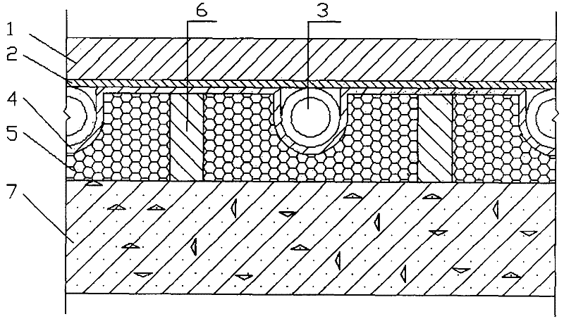
[0026] The floor structure is 110mm from bottom to top, the insulation layer is 25mm, the heating pipe is polybutene (PB) pipe, the outer diameter of the heating pipe is 12mm, the upper and lower heat conduction films are made of aluminum foil, the thickness is 0.1mm, and the wooden floor is 9mm. The heating tube spacing is 150mm. When the indoor design temperature is 18°C ​​and the average temperature of hot water in the heating pipe is 45°C, the average floor surface temperature is 27.9°C, the maximum temperature difference on the floor surface is 3.7°C, and the heat dissipation per unit floor area is 63W / m 2 .

Embodiment 2

[0028] The floor structure is 110mm from bottom to top, the insulation layer is 25mm, the heating pipe is polybutene (PB) pipe, the outer diameter of the heating pipe is 12mm, the thickness of the upper and lower heat conducting films is 0.2mm, and the wooden floor is 9mm. The heating tube spacing is 200mm. When the indoor design temperature is 20°C and the average temperature of hot water in the heating pipe is 50°C, the average floor surface temperature is 25.6°C, the maximum temperature difference on the floor surface is 2.6°C, and the heat dissipation per unit floor area is 59W / m 2 .

Embodiment 3

[0030] The floor structure is 110mm from bottom to top, the insulation layer is 40mm, the heating pipe is polybutene (PB) pipe, the outer diameter of the heating pipe is 20mm, the thickness of the upper and lower heat conduction films is 0.6mm, and the wooden floor is 9mm. The heating tube spacing is 200mm. When the indoor design temperature is 22°C and the average temperature of hot water in the heating pipe is 35°C, the average floor surface temperature is 26.2°C, the maximum temperature difference on the floor surface is 0.8°C, and the heat dissipation per unit floor area is 65W / m 2 .


PUM


Abstract

A dry hot water heating floor, belonging to the technical field of floor radioactive heating, comprises a floor decorative layer, an upper layer of metal heat conductive film, a heating pipe, a lower layer of metal heat conductive film, an insulated layer, a wood joist and a floor slab (or a ground). The heating pipe is adhered in an insulated material pipe groove, and is equipped with the metal heat conductive film extending around up and down so as to expand the heating surface thereof and make temperature of the floor surface uniform with reduced heat loss downwards; the wood joist has relative compact structure without hollow volume inside, so as to improve heat engineering mechanical property; the pipe diameter of the heating pipe is smaller than that of a heating pipe of an ordinarywet floor, but greater than that of a heating pipe of an integrated dry floor, so as to reduce thickness of construction layer and floor load, with low request of water quality, and low system resistance, and reduce cycle water bump power consumption. The floor structure can be pre-cast, or pre-cast partly, or assembled and paved in site, with simple construction, convenient maintenance, which isappropriate for new building heating, and building heat as well.

Description

technical field [0001] The invention relates to a structure of a dry hot water heating floor used for building heating, in particular to a double-layer metal heat-conducting film laid on the upper and lower sides of the heating pipe to increase the heat dissipation of the floor and improve the uniformity of the floor temperature, which is easy to install and maintain. The hot water heating floor structure with small floor load belongs to the technical field of floor radiant heating, and is suitable for both new building heating and existing building heating. Background technique [0002] Low-temperature hot water ground radiation heating uses hot water with a temperature not higher than 60°C as the heat medium, circulates in the heating pipe, heats the floor, and dissipates heat to the room through the ground through radiation heat exchange and convection heat exchange. Compared with the traditional convection heating method, the low-temperature hot water ground radiation he...

Claims


Application Information

Patent Timeline
Patent Type & Authority Patents(China)
IPC IPC(8): E04C2/52E04F15/02
Inventor 王随林闫全英潘树源史永征陈红兵李德英于丹
Owner 北京建筑工程学院
Why Eureka
Try Eureka