Supply unit
A power supply device and switching device technology, which is applied to output power conversion devices, electrical components, and irreversible AC power input to DC power output, etc. question
- Summary
- Abstract
- Description
- Claims
- Application Information
AI Technical Summary
Problems solved by technology
Method used
Image
Examples
Embodiment 1
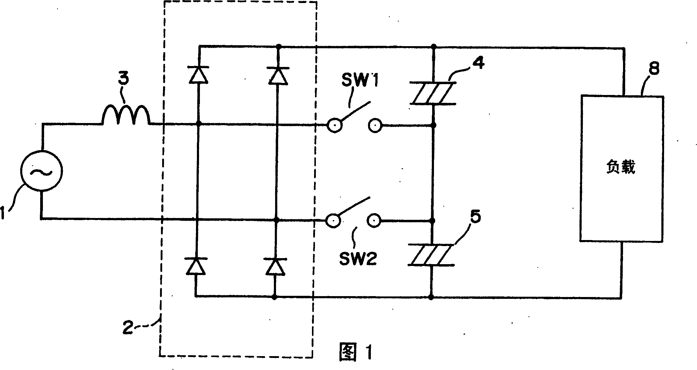
[0041] FIG. 1 is a circuit diagram for explaining the principle of the power supply device of the present invention.
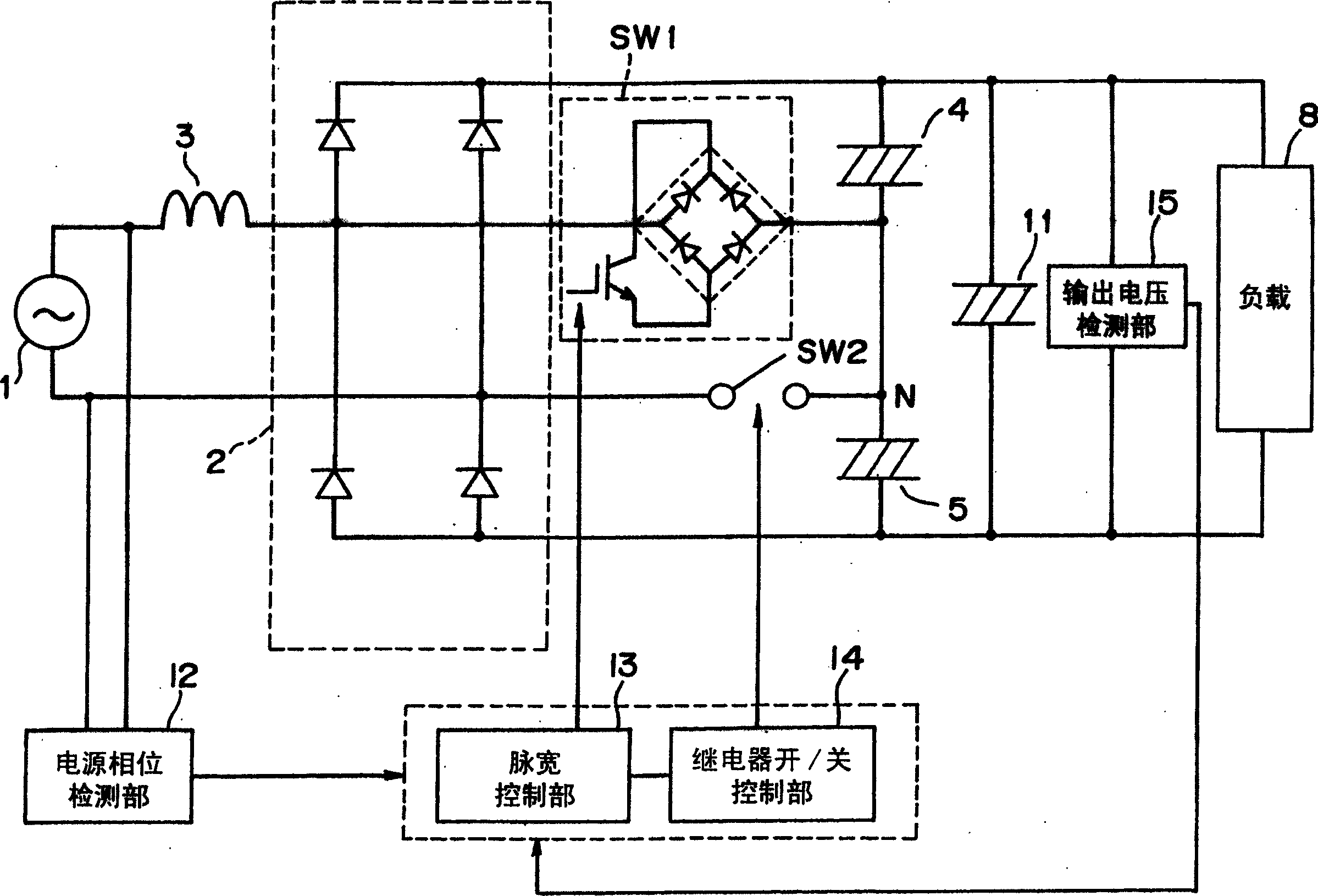
[0042]As shown in the figure, the power supply device includes: a rectifier circuit 2 that inputs and rectifies the voltage of the AC power supply 1 through a reactor 3; capacitors 4 and 5 for voltage doubler rectification; Switches SW1 and SW2 at the connection point between the capacitors 4 and 5 for voltage rectification. The power supply device rectifies the voltage from the AC power source 1 and outputs a DC voltage of a desired magnitude to the load 8 . The load 8 includes a transformer for driving a compressor of an air conditioner, a refrigerator, or the like, a DC motor used in a washing machine, and the like.
[0043] The rectifier circuit 2 consists of a half-bridge of two diodes. Capacitor 4 and capacitor 5 are connected in series, and are connected to the output terminal of rectification circuit 2 . The switches SW1 and SW2 are respectively con...
Embodiment 2
[0070] use Figure 9 Another example of the method of controlling the switches SW1 and SW2 in the operation mode of the power supply device will be described.
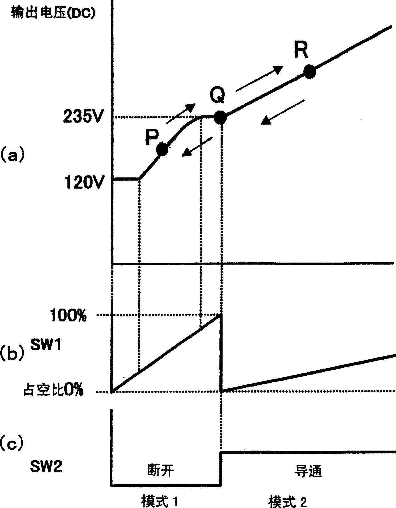
[0071] Figure 9 It is a waveform diagram illustrating the control of the respective switches SW1 and SW2 in this embodiment. Such as Figure 9 As shown, the control of mode 1 in this embodiment is the same as image 3 The same is true for Example 1 shown. However, in the control of mode 2, in embodiment 1, the switch SW2 is always turned on, and the switch SW1 is controlled by the pulse width, while in this embodiment, the switch SW1 is always turned on (that is, the occupied The duty cycle is set to 100%), so that the fluctuation of the corresponding output voltage of the bidirectional switch SW2 composed of a semiconductor switch is controlled by the pulse width.
[0072] As in the first embodiment, even when the switches SW1 and SW2 are controlled as described above, the input current waveforms before and afte...
Embodiment 3
[0077] In Example 1, such as Figure 4 As shown, "1-pulse control" in which only one control pulse is applied to the switch SW1 in a half cycle of the power supply voltage is performed. In this example, if Figure 11 As shown in FIG. 2 , control is performed to apply two control pulses to the switch SW1 within a half cycle of the power supply voltage (hereinafter referred to as "two-pulse control"). At this time, the previous pulse is applied when the zero-cross point of the power supply voltage appears, and the subsequent pulse is applied around the time when the input current becomes zero during 1-pulse control. In addition, the pulse width of the subsequent pulse is made smaller than that of the preceding pulse. By performing such 2-pulse control, the input current can be conducted not only in period A but also in period B, so that the power factor can be further improved and power supply efficiency can be improved.
PUM
 Abstract
Description
Claims
Application Information
 - R&D
- Intellectual Property
- Life Sciences
- Materials
- Tech Scout
- Unparalleled Data Quality
- Higher Quality Content
- 60% Fewer Hallucinations
Browse by: Latest US Patents, China's latest patents, Technical Efficacy Thesaurus, Application Domain, Technology Topic, Popular Technical Reports.
© 2025 PatSnap. All rights reserved.Legal|Privacy policy|Modern Slavery Act Transparency Statement|Sitemap|About US| Contact US: help@patsnap.com


