
Atomic beam phase contrast imaging device

A phase contrast imaging, atomic beam technology, applied in measurement devices, phase influence characteristic measurement, material analysis using wave/particle radiation, etc., can solve problems such as cannot be used to test phase changes

Inactive Publication Date: 2006-03-01
SHANGHAI INST OF OPTICS & FINE MECHANICS CHINESE ACAD OF SCI
View PDF0 Cites 2 Cited by
  • Summary
  • Abstract
  • Description
  • Claims
  • Application Information

AI Technical Summary

Problems solved by technology

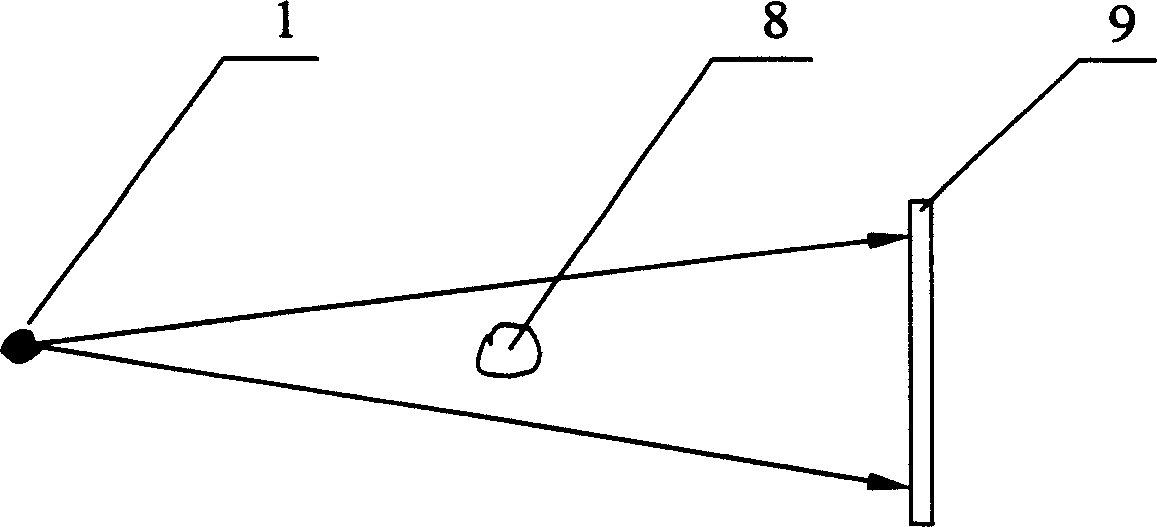
[0011] X-ray phase contrast imaging technology is very effective in detecting entities such as biological samples and materials, but it cannot be used to test phase changes such as electromagnetic fields, gravitational fields, etc.

Method used


Image

  • Atomic beam phase contrast imaging device
  • Atomic beam phase contrast imaging device
  • Atomic beam phase contrast imaging device

Examples


Embodiment Construction

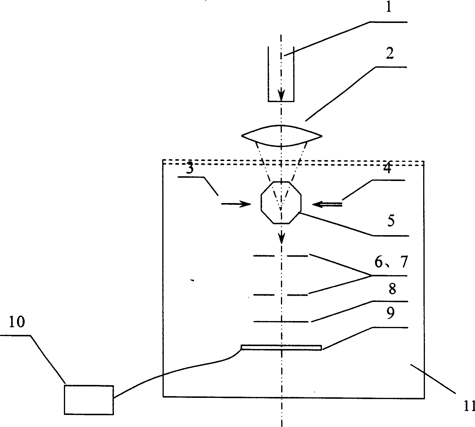
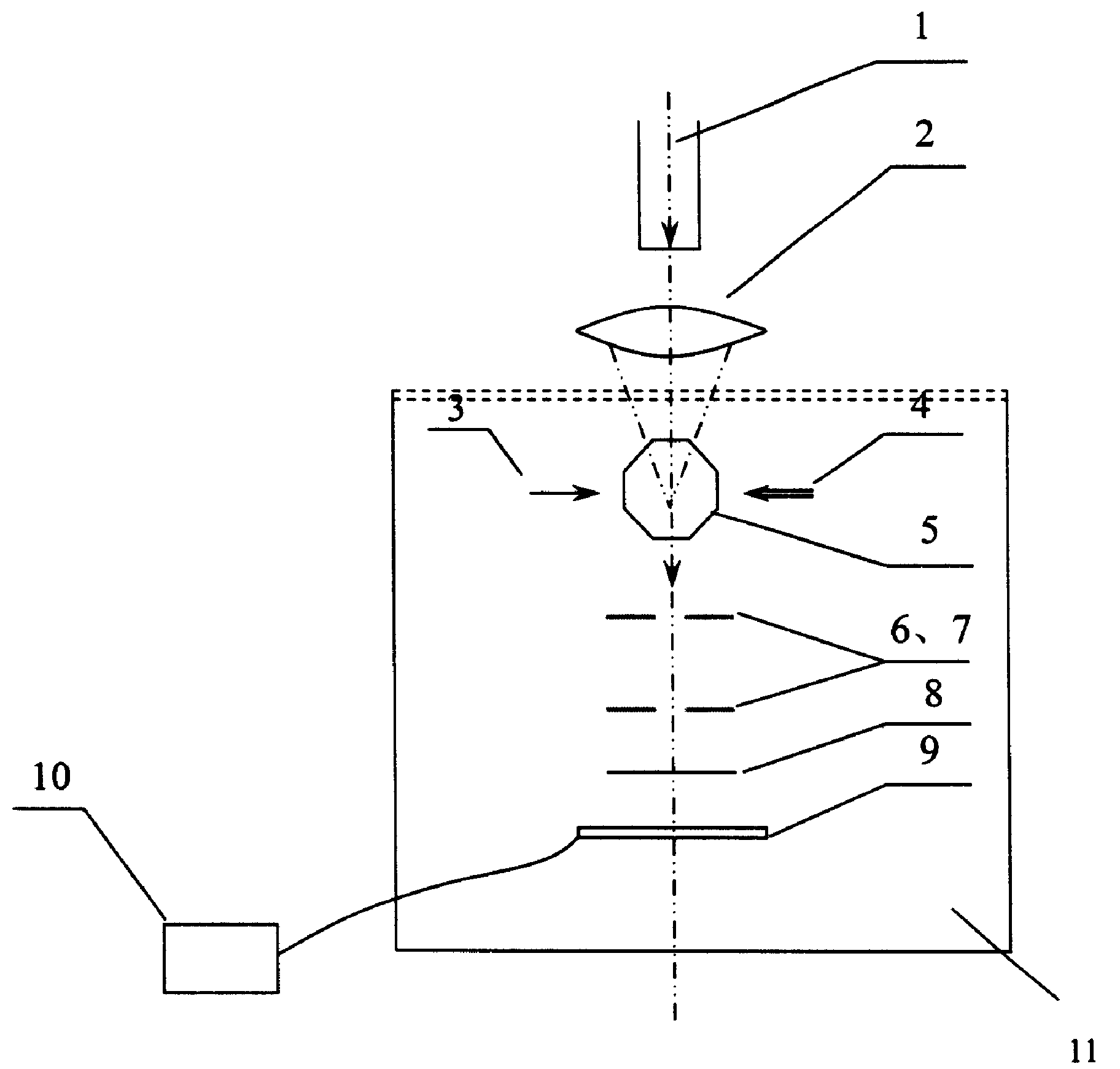
[0031] The atomic beam phase contrast imaging device of the present invention is as figure 2 As shown, it is composed of four parts, the first part is the atomic beam source, the second part is the sample to be tested, the third part is the recording and display device, and the fourth part is the vacuum system.

[0032] The first part of the atomic beam source, which contains seven parts: a laser 1 with a wavelength of 598nm, an optical lens 2, an Ne atom source 3, a dye laser 4 with a wavelength of 640mm, a magneto-optical cold mirror 5, the first pinhole diaphragm 6 and Second pinhole diaphragm 7.

[0033] The second part is the sample 8 to be tested.

[0034] The third part is the recording system 9 and the computer 10 .

[0035] The fourth part is the vacuum system 11 .

[0036] Said laser 1 has an output wavelength of 598nm, which is used to excite Ne atoms to a metastable state, namely: N e + hv → ...


PUM

PropertyMeasurementUnit
diameteraaaaaaaaaa

Abstract

The atomic beam phase contrast imaging device consists of four parts, including the first part of atomic beam source comprising 598 nm wavelength laser, optical lens, Ne atom source, 640 nm wavelength dye laser, magneto-optical cold mirror and two pinhole diaphragms; the second part of sample to be tested; the third part of record system, which includes micro channel board illuminated with atom beam in certain energy to generate electron and CCD to accept electron and in certain distance to the sample to be tested, and computer connected to CCD for showing the CCD accepted information; and the fourth part of vacuum system for the parts except laser, optical lens, Ne atom source, dye laser and computer to operate in. The device of the present invention is hopeful in measuring all the physical quantities capable of causing the phase change of atom beam, such as electromagnetic field, gravitational field, etc.

Description

Technical field: [0001] The invention relates to atomic beam imaging technology, in particular to an atomic beam phase-contrast imaging device, which can obtain phase information of a sample to be measured without using an interference method. Background technique: [0002] In recent years, due to the development of laser cooling deceleration technology and atomic diffraction grating manufacturing technology, it provides a technical basis for the study of atomic beam interferometers. In 1991, D.W.Keith of the Massachusetts Institute of Technology built a Ne atom interferometer with three transmission gratings for the first time. The first grating is used for beam splitting, the second grating is used for convergence, and the third grating is used for sampling. Its principle is similar to the early neutron interferometer structure. However, after two diffractions of this interferometer, the efficiency is very low, the structure is complicated, and adjustment is difficult, so...

Claims


Application Information

Patent Timeline
Patent Type & Authority Patents(China)
IPC IPC(8): G01N23/00G01N23/20G01N21/45
Inventor 陈建文高鸿奕李儒新谢红兰陆培祥徐至展
Owner SHANGHAI INST OF OPTICS & FINE MECHANICS CHINESE ACAD OF SCI
Learn More