Open-end rotor for rotor spinning machine

A technology of air spinning machine and rotor, which is applied to spinning machine, open-end spinning machine, continuous winding spinning machine, etc. It can solve problems such as unbalance, achieve increased productivity, increased number of revolutions, and better The effect of running performance

Inactive Publication Date: 2006-03-29
SAURER GERMANY GMBH & CO KG
View PDF2 Cites 0 Cited by
  • Summary
  • Abstract
  • Description
  • Claims
  • Application Information

AI Technical Summary

Problems solved by technology

Mainly unbalance problems arise because small dimensional deviations during the manufacture of the spinning rotors lead to larger unbalances in the case of larger diameters or larger masses

Method used


Image

  • Open-end rotor for rotor spinning machine
  • Open-end rotor for rotor spinning machine
  • Open-end rotor for rotor spinning machine

Examples


Embodiment Construction

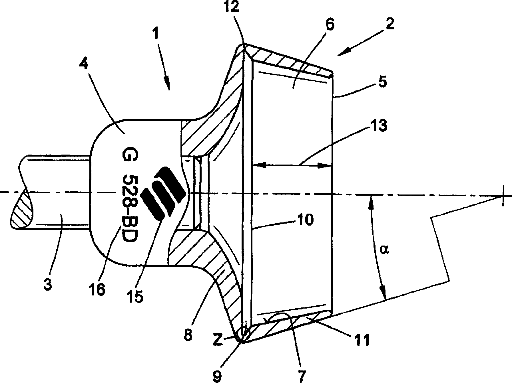
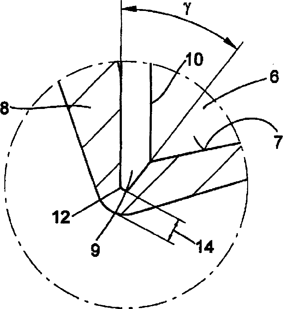
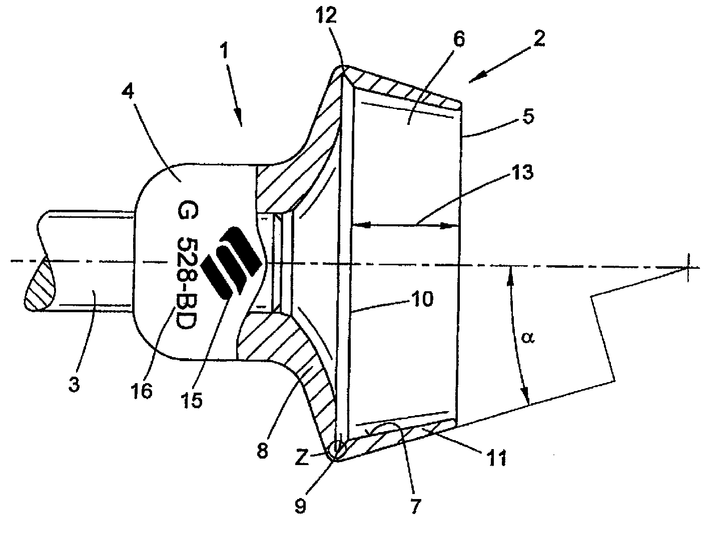
[0018] figure 1 Shown is a spinning rotor 1 with a fully turned rotor 2 which is fastened to a rotor shaft 3 . The rotor cup 2 can choose a casting part or a non-cutting casting part, and the required shape can be achieved by cutting. The rotor cup 2 is fastened to the rotor cup shaft 3 by means of a cup bottom projection 4 . The inner cavity 6 of the rotor cup 2 gradually expands in a conical shape from the cup mouth 5 opposite to the protruding part 4 to the turning groove 9 arranged on the circumference of the bottom 8 of the rotor cup and used as a fiber gathering groove, and has a to the inner side where the fiber sliding surface 7 acts. The fiber sliding surface 7 and the rotor groove 9 form a rib 10 where they meet. The rotor groove 9 is at a depth T13 measured from the cup mouth 5 . The ratio of the diameter of the cup opening 5 to the depth T13 is about 2.8:1.

[0019] The cup wall of the rotor cup 2 at the wall section 11 between the cup mouth 5 and the rotor cu...


PUM

PropertyMeasurementUnit
thicknessaaaaaaaaaa

Abstract

A spinning rotor for use at high speeds in open-end spinning machines has a rotor cup having an annular wall portion defining a rotor opening, a bottom wall portion merging with the annular wall portion, and a mounting hub extending exteriorly from the bottom wall portion. A rotor shaft is affixed to the mounting hub coaxially with the rotor cup. The merger of the bottom and annular wall portions of the rotor cup defines a maximum exterior diameter of the rotor and an interior rotor groove. The annular wall portion, the bottom wall portion and the mounting hub are of different cross-sectional thicknesses with the cross-sectional thickness of the bottom wall portion increasing from the rotor groove to the mounting hub. The wall thickness is less than 1.2 mm in the area of the maximum exterior diameter of the rotor cup (2) and the rotor cup has an aerodynamic exterior contour free of edges for deterring turbulent boundary layer air flow thereabout and an interior contour for promoting fiber spinning into a yarn.

Description

technical field [0001] The present invention relates to a rotor for an air-jet spinning machine. Background technique [0002] The ever-increasing demands on productivity have led to the development of today's open-end spinning machines beyond rotor speeds above 100,000 rpm. At such high rotational speeds, special demands are made on the unbalance of the spinning rotor, the bearing and the stability (risk of rupture). [0003] EP 0099490 B1 describes a chip-free formed rotor spinning rotor with a fiber gathering groove, suitable for high rotor speeds. In order to prevent the negative effects of centrifugal force generated by the rotor at high speed, such as the breakage or deformation of the spinning rotor, the outer circumference of the cup mouth edge should be designed as a crimp to increase the strength of such a known spinning rotor. With this reinforcement, the breaking revolutions of the spinning rotor can be increased. [0004] DE 19734637 A1 describes a rotor for ...

Claims


Application Information

Patent Timeline
Patent Type & Authority Patents(China)
IPC IPC(8): D01H4/10
CPCD01H4/10
Inventor H·-G·瓦森霍文H·格雷克施B·施勒默B·里德E·克拉克辛斯基
Owner SAURER GERMANY GMBH & CO KG
Why Eureka
Try Eureka