
Auxiliary driving motor

An auxiliary power and motor technology, applied in the direction of electric components, magnetic circuit rotating parts, control mechanical energy, etc., can solve the problems of power motor device failure, unsustainable power, large volume, etc., and achieve the effect of reliable use and increased stability

Inactive Publication Date: 2006-04-12
李宜和
View PDF1 Cites 0 Cited by
  • Summary
  • Abstract
  • Description
  • Claims
  • Application Information

AI Technical Summary

Problems solved by technology

[0002] Today's society is strongly advocating environmental protection and air purification, so that vehicles are all moving towards electric starting as the main direction of research. However, it is known that electric bicycles have shortcomings such as difficult control of power output, unsustainable power and excessive volume. This inventor once proposed to be 94112443.6 with the application number on August 15th, 94, and the name is called the invention patent application of auxiliary power motor to solve the above-mentioned problem, can refer to shown in the 8th, nine figures, it mainly consists of a flat shape and The fixed magnetic ring composed of stacked silicon steel sheets and multi-winding coils is fixed in the motor housing cover, and at least three HALL ICs are installed at the appropriate motor angular position of the fixed magnetic ring. The sensor is used to sense and generate the timing signal of the brushless commutation of the fixed magnetic ring, and the center of the motor cover is combined with one end of the wheel shaft, and an outer ring is composed of several magnets and is a flat rotor inside the motor. The disk is mounted on the wheel shaft, and a corresponding speed sensor is installed between the outside of the motor housing cover and the wheel cover to feed back the wheel speed to a programmable counting control circuit, and the control circuit reaches a preset value according to the wheel speed When the speed is high, a motor control circuit is activated to provide three-phase power to the stator ring to make the rotor disk rotate, and the rotor disk transmits the wheel cover through a hollow shaft and a planetary gear set for deceleration to form an auxiliary power structure Known from the above, although the previous case has excellent efficacy and relatively small volume, it still has the following shortcomings for improvement after being used by the public for a long time:
[0003] 1. The magnets on the outer surface of the rotor disk are glued with bonding medium. When the rotor disk rotates at high speed for a long time and vibrates, or the bonding medium does not stick for a long time and causes peeling off, the power motor device will fail.
[0004] 2. The circuit board used is fixed on the car body, which is more likely to be damaged by collision, and because it is separated from the auxiliary power motor, it is not easy to install, and this separate design is also likely to affect the appearance of the car body

Method used


Image

  • Auxiliary driving motor
  • Auxiliary driving motor
  • Auxiliary driving motor

Examples


Embodiment

[0021] Example An auxiliary power motor

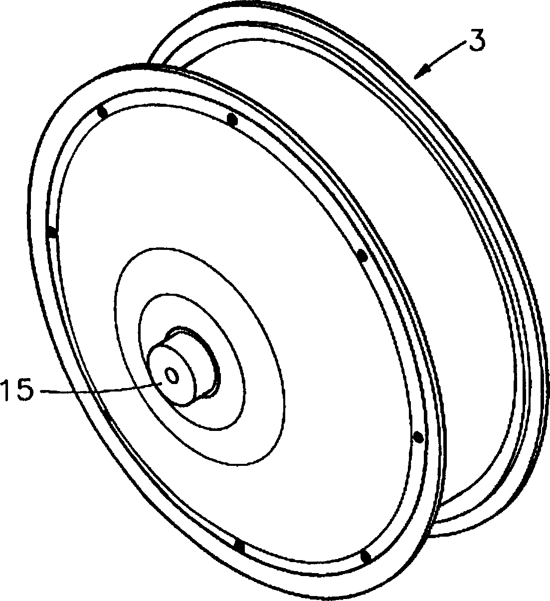
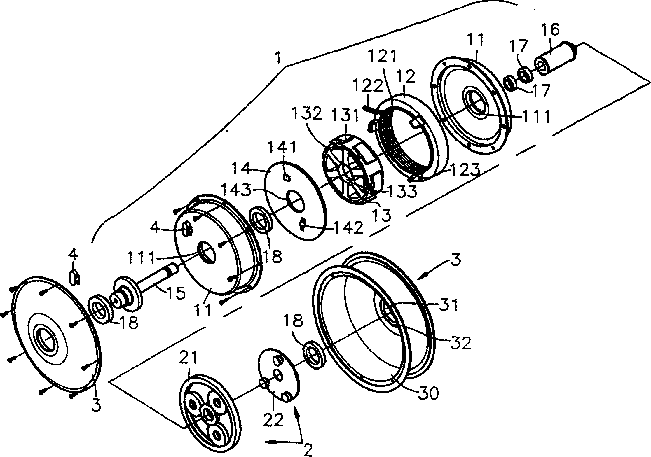
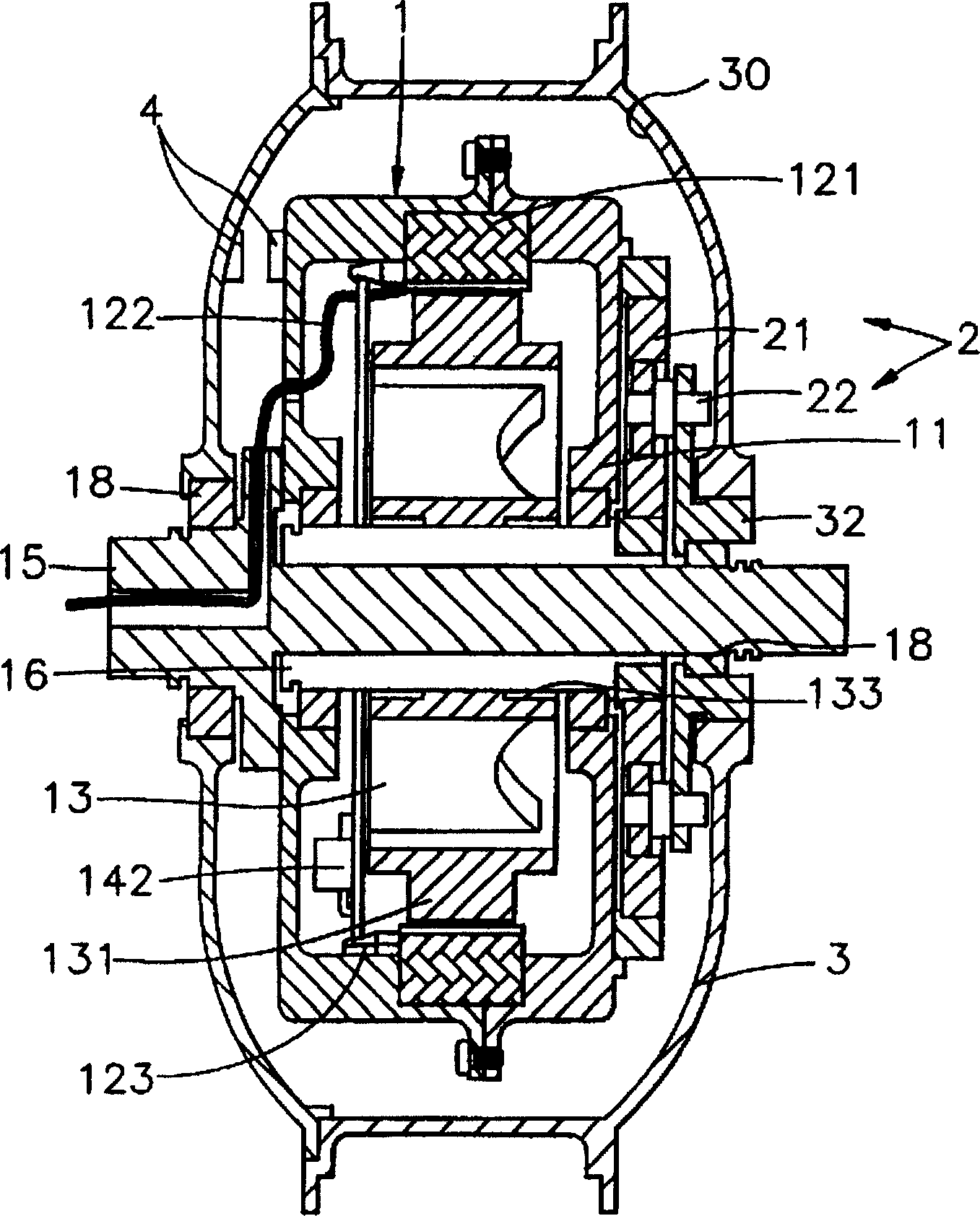
[0022] Please refer to Figures 1, 2, 3, and 4. It can be clearly seen from the figures that an auxiliary power motor in this embodiment includes an auxiliary power motor device 1, a reduction mechanism 2 and a wheel cover 3; wherein:

[0023] The accommodating space 30 of the wheel cover 3 is for accommodating the auxiliary power motor device 1 therein, and the fixed magnetic ring 12, the rotor disk 13 and the circuit board 14 are accommodated between the two shells 11 of the auxiliary power motor device 1. Inside, a plurality of stators 121 are provided at the inner diameter of the fixed magnetic ring 12, and the signal line 122 at the stator 121 is used to control whether there is electrical conduction, and a rotor disc 13 is placed inside the fixed magnetic ring 12, and the outer ring of the rotor disc 13 is A plurality of T-shaped tooth parts 131 are arranged facing upward, and accommodating chamber 130 is formed in the gap between...


PUM


Abstract

This invention is related to an auxiliary power motor put under the outer cover of a wheel and a rotated sensor set between the outer cover of the wheel and the motor to measure the speed of the rotor then to turn-on the static magnetic ring of the auxiliary motor and to rotate the disk in the middle of the static magnetic ring when the speed of the rotor gets the pre-set value, thereto give an auxiliary force to the single-row bearing connected with the side of a rotating driving shaft to force the outer cover of the wheel rotate thereafter. The above mentioned rotor disk outer surface is set several T-shape of teeth with a magnet set in-between the two adjacent T-shape teeth to avoid effectively magnet separation from the rotor disk caused by centrifugal force as the rotor disk rotates at high speed.

Description

technical field [0001] The invention provides an auxiliary power motor, especially an auxiliary power motor applied to wheels, and the auxiliary power motor is a brushless commutation design, wherein the plurality of magnets positioned on the outer circumferential surface of the rotor disk with a fixed magnetic field can effectively avoid A kind of auxiliary power motor in which a plurality of magnets are separated from the rotor disk due to the influence of centrifugal force. Background technique [0002] Today's society is strongly advocating environmental protection and air purification, so that vehicles are all moving towards electric starting as the main direction of research. However, it is known that electric bicycles have shortcomings such as difficult control of power output, unsustainable power and excessive volume. This inventor once proposed to be 94112443.6 with the application number on August 15th, 94, and the name is called the invention patent application of...

Claims


Application Information

Patent Timeline
IPC IPC(8): H02K1/27H02K7/116H02K1/12H02K29/08
Inventor 李宜和
Owner 李宜和
Learn More