Method of clamping and anchoring high strength composite material

A composite material, high-strength technology, applied in the direction of thin plate connection, connecting components, mechanical equipment, etc., can solve the problems of complex manufacturing process, inconvenient promotion and application, high cost, etc., and achieve simple manufacturing process, good applicability, and convenient operation. Effect

Inactive Publication Date: 2006-04-19
卓静
View PDF1 Cites 0 Cited by
  • Summary
  • Abstract
  • Description
  • Claims
  • Application Information

AI Technical Summary

Problems solved by technology

Due to the complex manufacturing process, large size, poor reliability and high cost of these methods, it is not easy to be widely used in engineering applications.

Method used


Image

  • Method of clamping and anchoring high strength composite material
  • Method of clamping and anchoring high strength composite material
  • Method of clamping and anchoring high strength composite material

Examples


Embodiment Construction

[0030] Below in conjunction with embodiment, further illustrate the present invention.

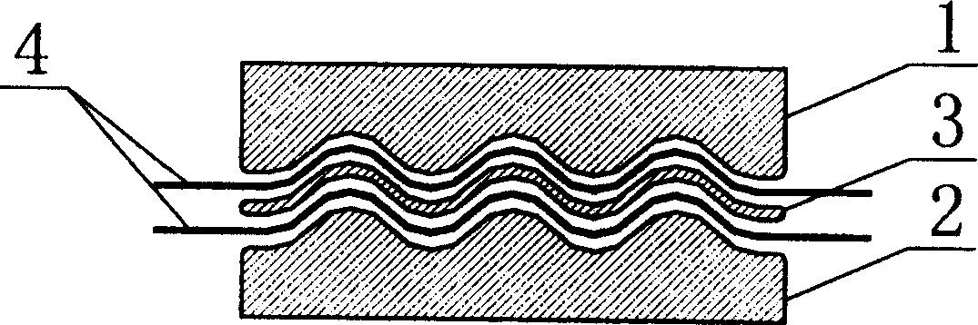
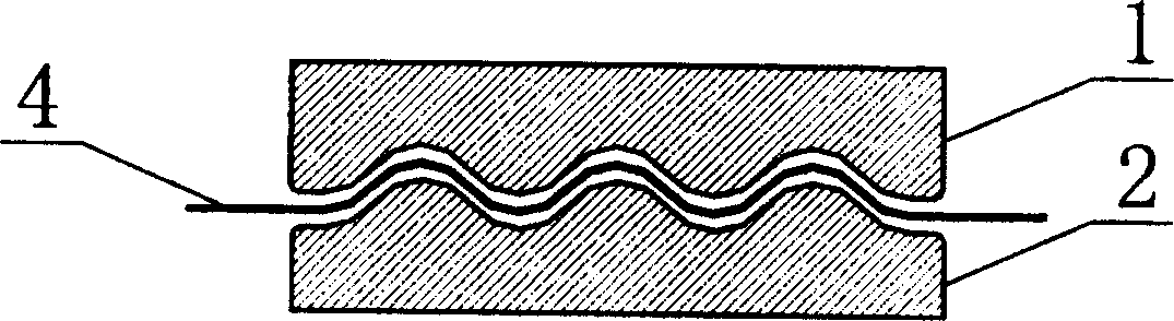
[0031] like figure 1 , 3 As shown, the method steps for clamping and anchoring the thin carbon fiber composite sheet are as follows:

[0032] Step One: Choose the Shape of the Clamp Anchor

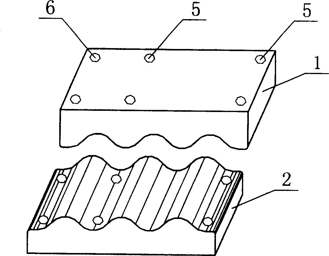
[0033] Since this embodiment is to clamp and anchor the carbon fiber cloth sheet, and the carbon fiber cloth sheet is relatively thin and the number of layers is small (that is, 2×0.111mm), so this embodiment chooses a parallel linear wave-tooth clamp anchor , and no stiffening corrugated plates are added.

[0034] In this embodiment, four steel plates with a length of 200 mm, a width of 100 mm and a thickness of 25 mm are used to make two upper corrugated tooth plates 1 and lower corrugated tooth plates 2 respectively to form two corrugated tooth clamp anchors. Each corrugated tooth jig anchor is composed of an upper corrugated tooth plate 1 and a lower corrugated tooth plate 2 matched with each o...


PUM


Abstract

A new method to hold and anchor high-strength composite utilizes holder anchor with waved teeth to hold and anchor the composite firmly and reliably so problem of holding and anchoring for composite sheet has been solved.

Description

1. Technical field [0001] The invention belongs to the technical field of clamping and anchoring of high-strength composite materials. 2. Background technology [0002] High-strength composite materials, such as carbon fiber-reinforced plastics, polymer fiber-reinforced plastics, glass fiber-reinforced plastics, etc., are composite materials composed of high-strength fibers as reinforcements and resin as a matrix. Because high-strength composite materials have light weight, high strength, low creep, low thermal expansion coefficient, moderate elastic modulus, and good corrosion resistance and fatigue resistance, they are widely used, especially in the manufacture of cable structures, bearing It has a large force capacity and is an ideal substitute for prestressed steel wire bundles. Composite materials can be divided into three categories in terms of usage form: sheet, rod and grid, among which sheet is further divided into cloth and plate. The manufacture and application ...

Claims


Application Information

Patent Timeline
Patent Type & Authority Patents(China)
IPC IPC(8): F16B5/00F16B11/00
Inventor 卓静
Owner 卓静
Why Eureka
Try Eureka