On-line turbogenerator stator winding end portion vibration monitoring device and its application

A turbogenerator and stator winding technology, applied in the direction of instruments, etc., can solve the problems of electromagnetic field interference, self-vibration and wear, and inability to make close contact with sensors, and achieve the effects of low lateral sensitivity, long service life, and stable amplitude

Inactive Publication Date: 2006-05-03
ELECTRIC POWER RES INST OF GUANGDONG POWER GRID
View PDF0 Cites 2 Cited by
  • Summary
  • Abstract
  • Description
  • Claims
  • Application Information

AI Technical Summary

Problems solved by technology

At present, there are two common methods: one is to install the sensor directly on the insulator at the end of the generator stator, which mainly has the following disadvantages: (1) The sensor itself does not take insulation and shielding measures, not only cannot be used in high potential It is difficult to accurately reflect the vibration and wear of the measured stator winding; (2) It is difficult for the sensor to be fixed on the measured stator winding, which is easy to cause its own vibration and wear
The second is to set an insulating layer at the nose of the neutral point bar of the sensor and the measured stator winding, which mainly has the following disadvantages: because the insulating layer and the sensor are not connected as a whole, on the one hand, the entire sensor part is very bulky , occupies a large space at the nose of the stator, causing the test results to be inconsistent with the actual situation. On the other hand, the measured stator winding cannot be in close contact with the sensor, so it is difficult to accurately measure the vibration and wear of the measured stator winding

Method used


Image

  • On-line turbogenerator stator winding end portion vibration monitoring device and its application
  • On-line turbogenerator stator winding end portion vibration monitoring device and its application
  • On-line turbogenerator stator winding end portion vibration monitoring device and its application

Examples


Embodiment Construction

[0033] The specific implementation method of the present invention is described in detail below.

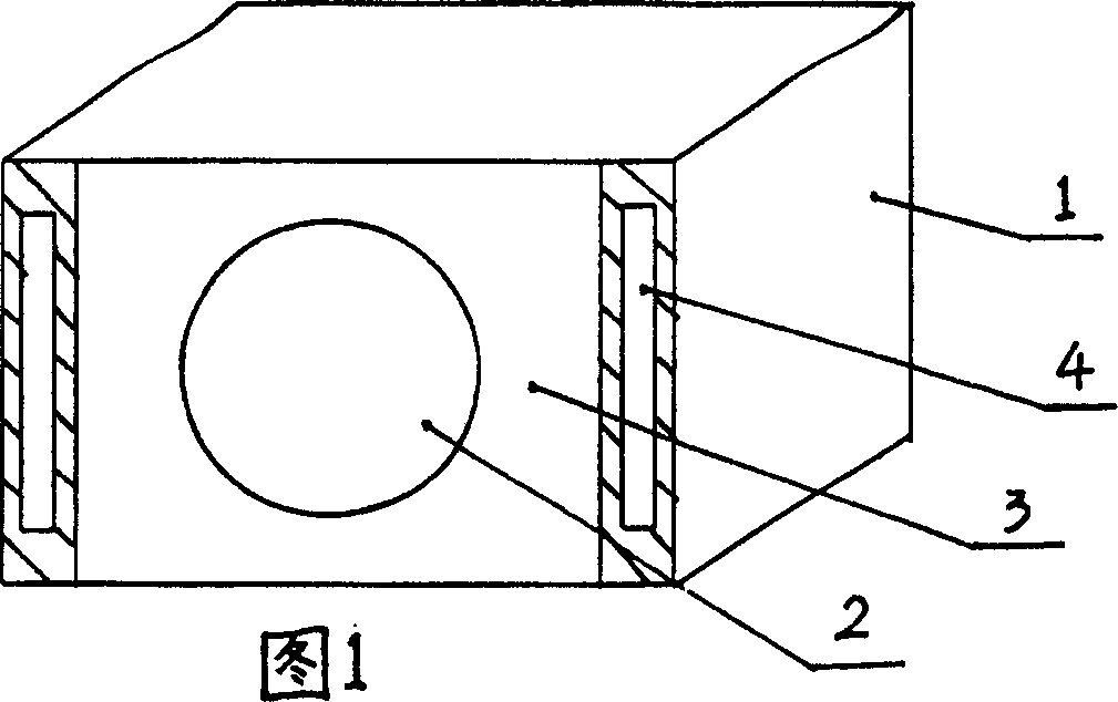
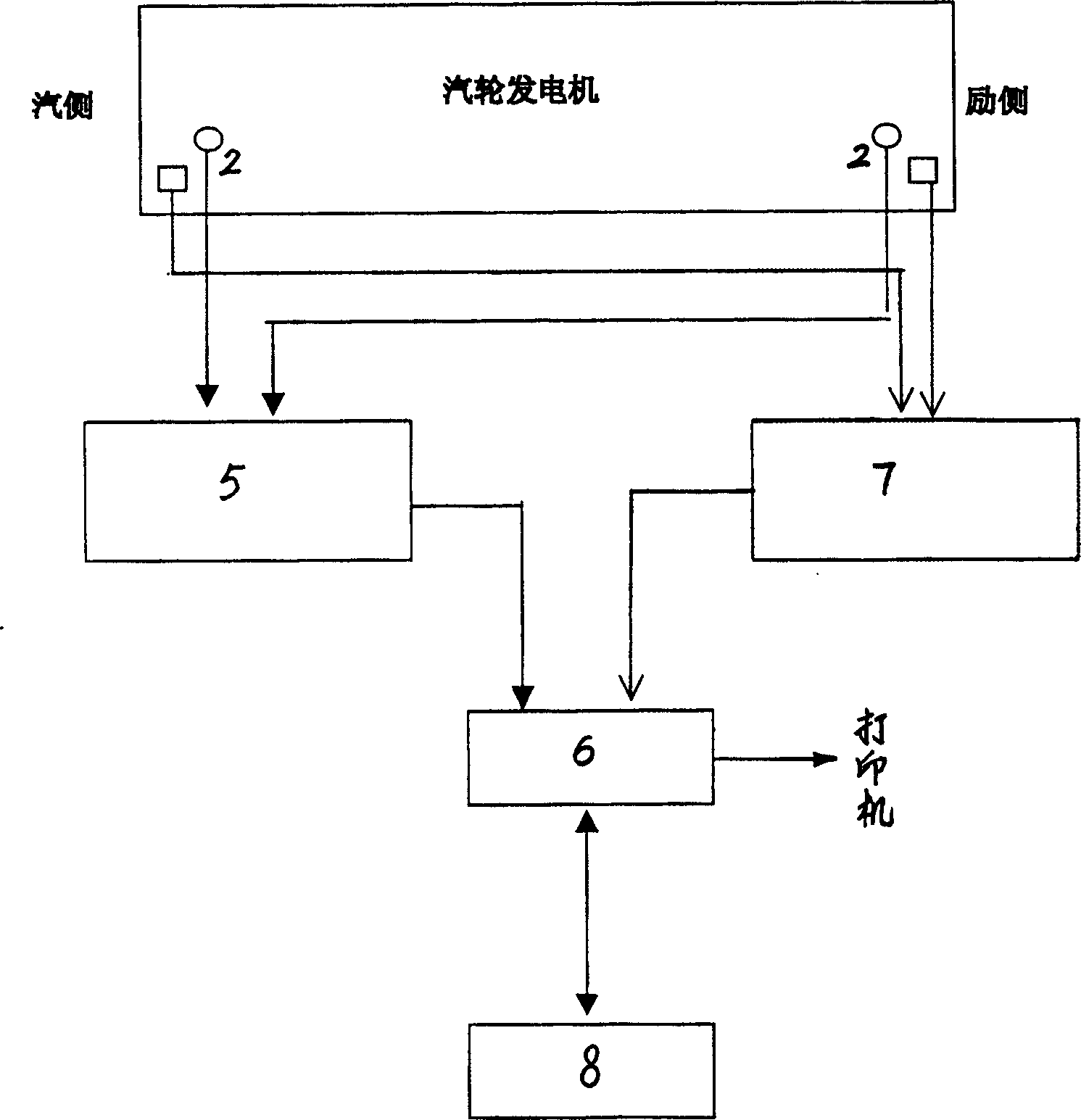
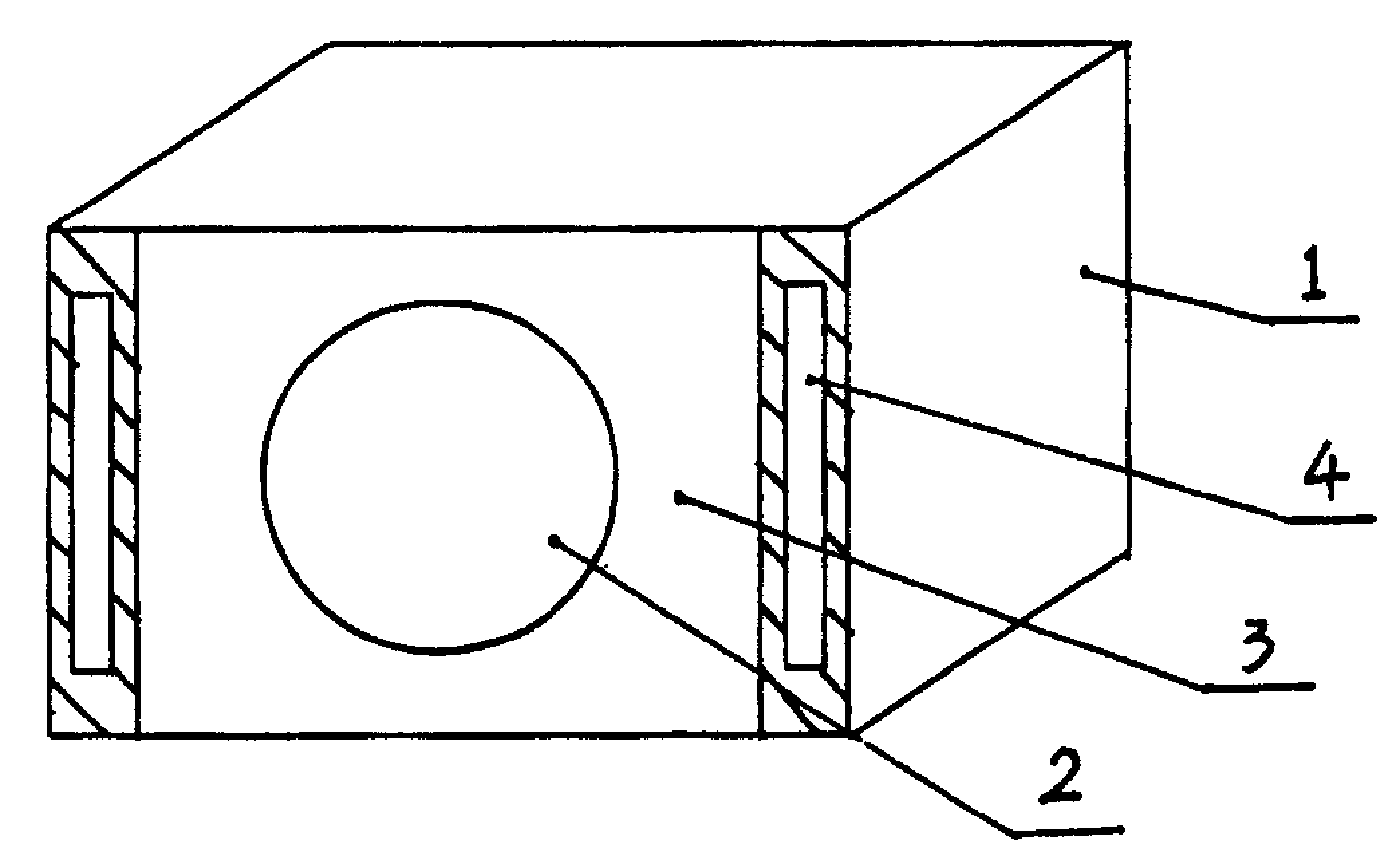
[0034] figure 1, figure 2 It is an embodiment applied to No. 3 generator of Guangdong Shajiao Power Plant A. As can be seen from Fig. 1, the monitoring device in this embodiment is composed of a pressure sensor 2 and an insulating box 1, the pressure sensor 2 is built in the insulating box 1, and the insulating box 1 is made of epoxy resin, and a cylindrical cavity is arranged in the box. The cavity and the sensor are placed in the cavity, and a metal shielding layer 3 is arranged on the sensor 2, and the sensor 2 and the shielding layer 3 are cured into a whole with epoxy resin; grooves 4 are arranged on the outside of the insulating box 1, and the sensor 2 The signal output end of the signal is drawn out of the insulation box 1 through the shielded cable; through the groove 4, the insulation box 1 with the sensor 2 is bound to the outlet nose of the stator winding to be measur...


PUM


Abstract

The invention relates to an on-line monitoring device for the vibration of the stator winding end of a turbogenerator set and a method for using it, and is characterized in that it is composed of an insulating box (1) and an acceleration sensor (2) arranged in the insulating box (1), and the insulating box (1) Made of epoxy resin, the insulating box (1) is provided with a cylindrical cavity, the acceleration sensor (2) is placed in the cavity, and a metal shielding layer (3) is arranged on the acceleration sensor (2). The epoxy resin cures the sensor (2) and the shielding layer (3) into a whole; the outer side of the insulating box (1) is provided with a groove (4), and the signal output end of the acceleration sensor (2) leads out of the insulating box through a shielded cable (1) outside; the insulating box (1) with the acceleration sensor (2) is bound to the wire rod nose end of the measured stator winding through the groove (4), the acceleration sensor (2) detects the vibration of the stator winding, and The vibration signal is converted into an electrical signal and transmitted to the peripheral detection equipment through the shielded cable.

Description

technical field [0001] The invention relates to an on-line monitoring device and a using method for the vibration at the end of a stator winding of a steam turbine generator set. The utility model belongs to the technical field of generator detection in electric power industry. Background technique [0002] The end of the stator winding of a large turbogenerator bears the alternating electromagnetic force during normal operation and the huge transient electromagnetic force during outlet or internal short circuit. With the increase of the unit capacity of the generator, the effect of the electromagnetic force also increases rapidly, and the huge electromagnetic force causes more and more harm to the end structure. Various statistical data show that: due to insufficient end strength and vibration and wear during operation, the sudden accidents caused by large turbogenerator stator windings account for the majority. Studies have shown that there is 100Hz elliptical electromag...

Claims


Application Information

Patent Timeline
Patent Type & Authority Patents(China)
IPC IPC(8): G01M7/00
Inventor 杨楚明周尚礼
Owner ELECTRIC POWER RES INST OF GUANGDONG POWER GRID
Why Eureka
Try Eureka