Connector for module

A connector and connection state technology, applied in the direction of connection, two-part connection device, parts of connection device, etc., can solve problems such as unstable operation of semiconductor memory, poor contact of modules, plastic deformation of wrist, etc.

Inactive Publication Date: 2006-06-07
JST MFG CO LTD
View PDF0 Cites 1 Cited by
  • Summary
  • Abstract
  • Description
  • Claims
  • Application Information

AI Technical Summary

Problems solved by technology

Therefore, the arm of the connector is deformed by receiving this heat load, and the locking function formed by the locking part may be damaged.
Furthermore, the operation of elastically deforming the tip of the wrist toward the outside with the fingers may cause plastic deformation of the wrist.
In short, these are the problems that will cause the so-called poor contact and falling off of the module.
[0004] Moreover, there is a problem that the operation of the semiconductor memory becomes unstable due to heat generation
In addition, if the influence of electromagnetic waves, etc., is received from the surroundings of the connector, the operation of the circuit may become unstable.

Method used


Image

  • Connector for module
  • Connector for module
  • Connector for module

Examples


no. 6 Embodiment

[0075] In the sixth embodiment, there is an embodiment in which the present invention is applied to a connector at a portion not linked to the lifting and lowering of the rear end of the metal cover 220 of the supporting portion 213, and the same operations and effects as those in the first embodiment can be obtained.

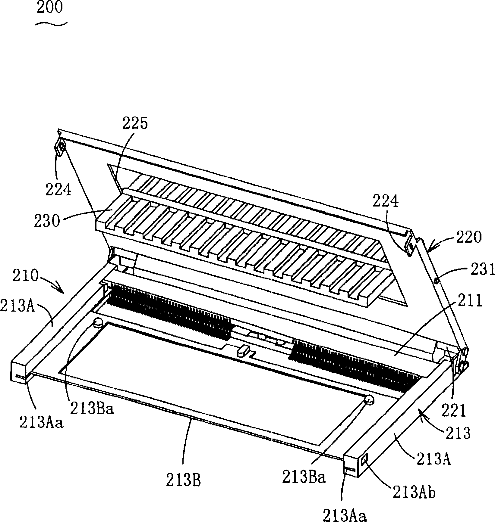
[0076] 35 to 37B show the seventh embodiment. In the seventh embodiment, there is no movable part that slides on the support part 213 as in the sixth embodiment, and there is no part in the support part 213 that is interlocked with the raising and lowering of the rear end of the metal cover 220 . Furthermore, the metal cover 220 is not hingedly coupled to the access portion 211 , and is designed to be freely attachable to and detachable from the connector body 210 . In the support piece 228 hanging down from the left end side and the right end side of the metal cover 220, an inverted L-shaped guide groove 228a is formed at the lower end. In addition, the conne...

Embodiment 7

[0079] In Embodiment 7, the metal cover 220 is not hingedly combined with the access portion 211. In the embodiment in which the connector body 210 is set to be freely detachable, regardless of the application of the present invention, the same result as in Embodiment 1 can be obtained. role and effect. In addition, when the metal cover 22 is removed, the contacts 212a and 212b are exposed and can be easily recognized by the eyes, so that the insertion operation of the substrate 110 is facilitated.

[0080] FIG. 38 shows Embodiment 8. FIG. In Example 8, with figure 1 In the same embodiment, the metal cover 220 is hingedly combined with the access portion 211 . Furthermore, the metal cover 220 is detachably attached to the connector body 210 by separating this hinge structure. On the left and right sides of the insertion portion 211, there are provided contact walls 260 protruding upward. Here, the receiving wall 260 is provided with a receiving hole 261 penetrating in the ...

Embodiment 8

[0082] In Embodiment 8, the metal cover 220 is not hingedly combined with the access portion 211. In the embodiment in which the connector body 210 is set to be freely removable, regardless of the application of the present invention, the same result as in Embodiment 1 can be obtained. role and effect. In addition, removing the metal cover 220 exposes the contacts 212a and 212b and makes them easy to recognize with the eyes, so that the insertion operation of the substrate 110 is facilitated.

[0083] The present invention includes embodiments combining the features of the above embodiments.

[0084] Through the description of these embodiments, the first module connector mentioned in the outline of the present invention has been fully disclosed. Moreover, the connectors for the second and third modules described below have been fully described by the description of these embodiments.

[0085] That is, in the connector for the second module, in the connector for the first mo...


PUM


Abstract

A connector for a module, the connector includes: a connector body, the connector body includes an access part; a contact point provided in the access part; a support part for loading a module and restricting its forward, backward, left, and right movement; a metal The cover is covered and locked on the connector body, and holds the module between the supporting part to maintain the connected state. It has a window for exposing the semiconductor chip of the connected module and a heat dissipation plate. In order to prevent problems such as poor contact with the module due to thermal load, the antimagnetic function is used to reduce the influence of electromagnetic waves on the connector to maintain the stability of the circuit operation, and to cool the semiconductor chip to maintain its operation stability.

Description

technical field [0001] The present invention relates to a module connector, especially a module connector (abbreviated as connector hereinafter) in which a semiconductor chip is mounted on a square substrate and a conductive pad is provided on the front side of the substrate. Specifically, it deals with solutions to heat, electromagnetic waves, etc. of connectors for modules. Background technique [0002] Conventionally, such a module, such as a semiconductor chip, is known as a module on which a semiconductor memory is mounted, and a connector for a module in which the board surface is connected in a state substantially parallel to a printed circuit board such as a main board has been widely used. use. This connector roughly forms a ㄈ shape with respect to the front, left and right sides of the module. A groove for receiving the front side of the module is formed at the receiving portion corresponding to the front side. In this groove, from when the module is in the conn...

Claims


Application Information

Patent Timeline
Patent Type & Authority Patents(China)
IPC IPC(8): H01R12/14H01R12/22H01R12/18H01R13/00H01R13/62H01R13/658H05K7/20H05K9/00H01R24/00G06K19/077H01R12/72H01R12/88H01R13/514H05K7/14
CPCH01R12/721H01R12/88H05K7/1431H01R13/514
Inventor 安福薰保坂泰司宫泽雅昭
Owner JST MFG CO LTD
Why Eureka
Try Eureka