Check patentability & draft patents in minutes with Patsnap Eureka AI!

Circuit layout

A circuit layout, printed circuit board technology, applied in the direction of circuits, printed circuit components, electrical components, etc., can solve the problems of reducing current carrying capacity and increasing ohmic resistance

Inactive Publication Date: 2006-07-12
SEMIKRON ELECTRONICS GMBH & CO KG
View PDF0 Cites 0 Cited by
  • Summary
  • Abstract
  • Description
  • Claims
  • Application Information

AI Technical Summary

Problems solved by technology

The temperature rise of the AC connection elements leads there to an increase in the ohmic resistance and thus to a reduction in the current-carrying capacity

Method used


Image

  • Circuit layout
  • Circuit layout
  • Circuit layout

Examples


Embodiment Construction

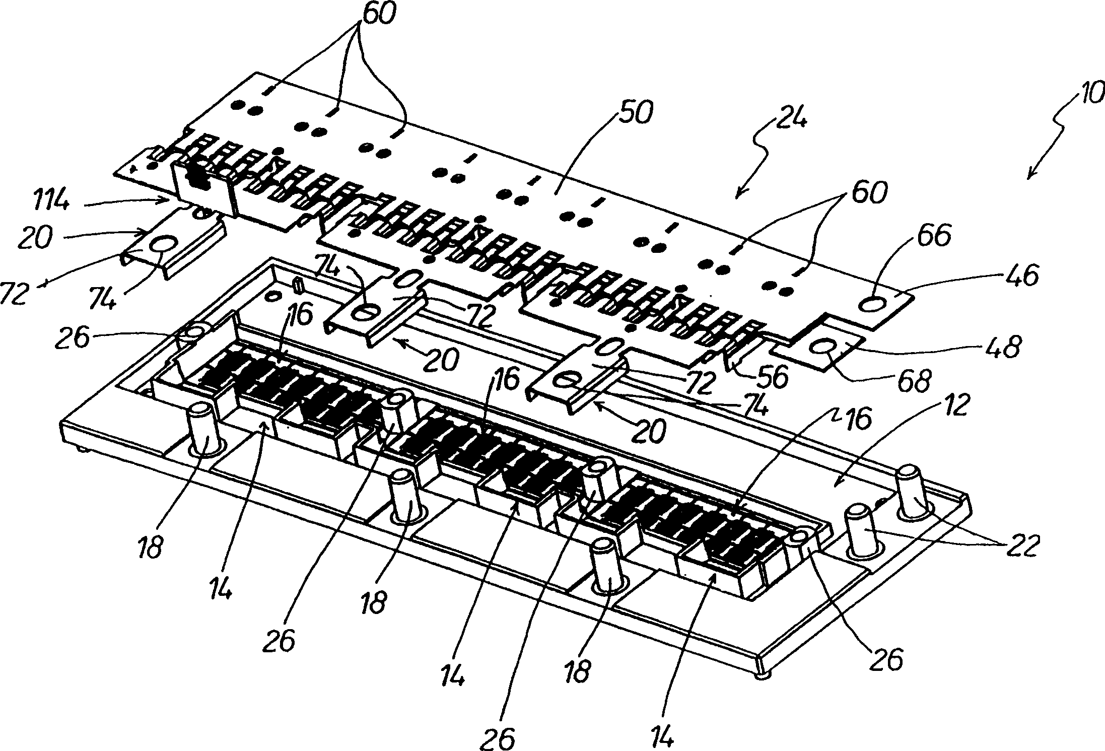
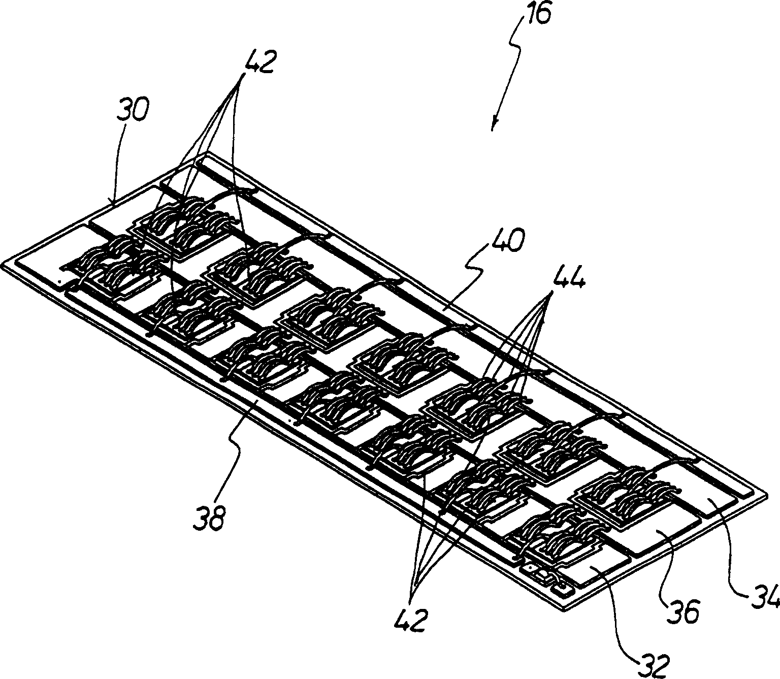
[0024] figure 1 An important part of the structure of the circuit arrangement 10 with a substrate 12 is shown. The frame-like base body 12 is mounted on a cooling element, which has three compartments 14 separated from each other. Each compartment 14 is intended for one substrate 16 . exist figure 2 Such a substrate 16 is shown in FIG. 1 and described in detail later.

[0025] Standing upwards from the base body 12 are plugs 18 which are provided for precise positioning of the associated AC connection element 20 . exist Figure 4 Such an AC connection element 20 is shown in FIG. 1 and will be described in detail later.

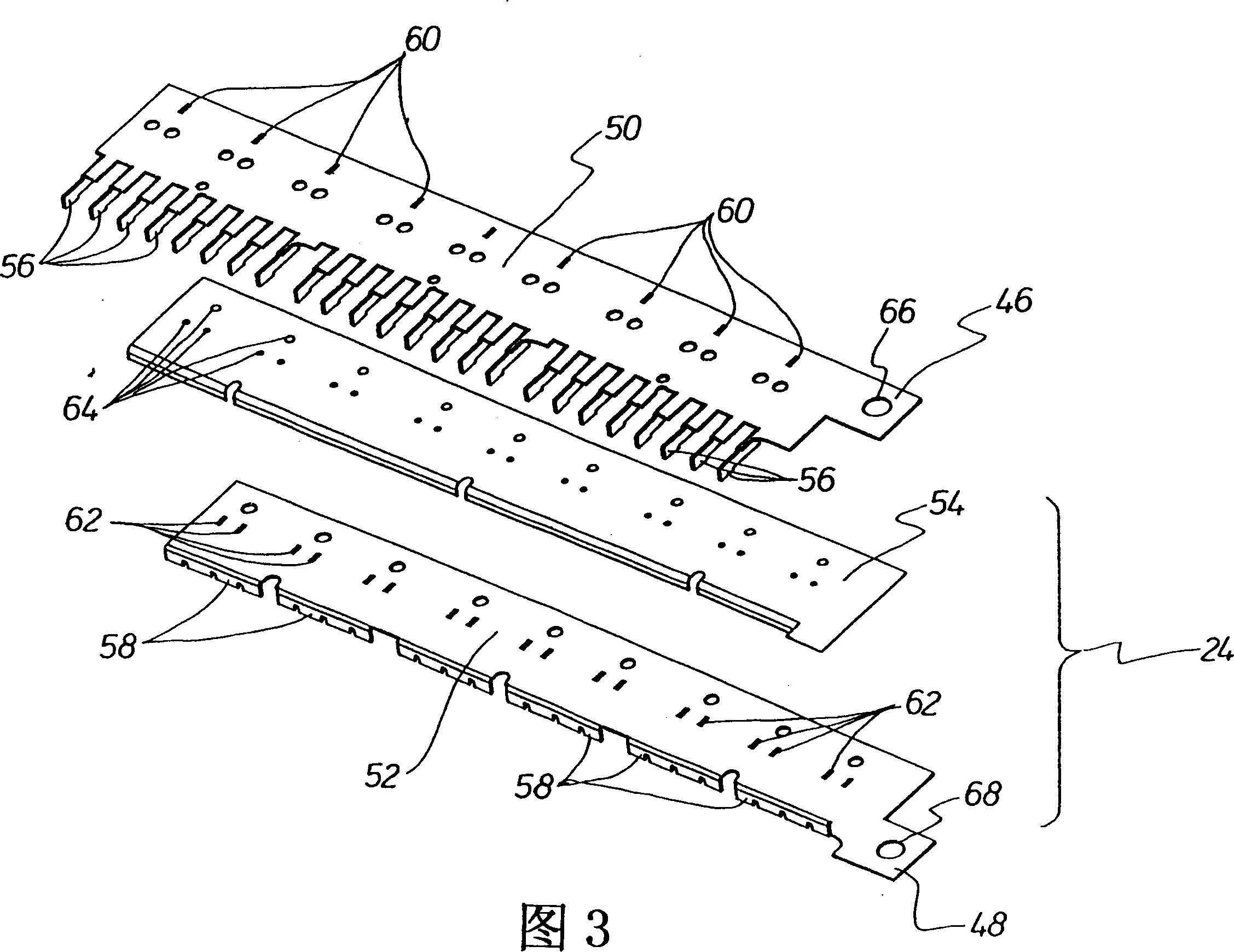
[0026] Furthermore, two plugs 22 protrude upwards from the base body 12 and are provided for precise positioning of the intermediate printed circuit board 24 . Such an intermediate printed circuit board 24 - without associated capacitors - is shown in the perspective exploded view in FIG. 3 and will be explained in more detail below.

[0027] Threaded ...


PUM


Abstract

The present invention relates to a circuit arrangement (10) includes a base body (12), with one or more substrates (16), an intermediate-circuit board (24), a compression device (28) and a driver circuit. Each substrate (16) includes a positive-pole conductive strip (32), a negative-pole conductive strip (34), an AC conductive strip (36), and auxiliary connections (38, 40). Components (42) such as power transistors are in contact with the conductive strips and the auxiliary connections. The intermediate-circuit board (24) includes a positive-pole DC connection (46) and negative-pole DC connection (48) and electrical capacitors connected between them. An AC connection element (20) that must be cooled is assigned to each substrate (16). The positive-pole DC connection (46) and the negative-pole DC connection (48) include contacts (56 or 58) for direct low-inductance connection with the corresponding conductive strips (32 and 34) of the one or more substrates (16). The equivalent applies to the one or more AC connection elements (20). The compression device (28) electrically connects the contacts (70) of the positive-pole and negative-pole DC connections (46 or 48) and the contacts (56, 58) of the one or more AC connection elements (20).

Description

technical field [0001] The invention relates to a circuit arrangement comprising a base body; at least one substrate with positive, negative and alternating current conductor tracks and auxiliary connections on its upper side; components such as transistors, thyristors , diodes, resistors, integrated circuits or sensors, which are at least partially in contact with these printed conductors; an intermediate printed circuit board, which has a positive DC connector, a negative DC connector and at least one connection between the positive DC connector and the negative DC connector between the capacitors; and including at least one AC connection. Background technique [0002] The older patent application DE 100 37533.2 describes a circuit arrangement with low parasitic inductance, which comprises an electrically insulating substrate, metallic conductor tracks electrically insulated from one another on the substrate, and circuit breakers mounted thereon. There, the circuit breake...

Claims


Application Information

Patent Timeline
IPC IPC(8): H01L25/07H01L25/065H01L23/48H05K1/18H05K7/20H01L25/16H01L25/18H05K1/02
CPCH01L2924/30107H01L2924/01074H01L25/162H01L2924/01006H01L2924/01004H01L2924/01002H01L2924/01082H01L2924/01015H01L2224/49111H01L2924/01033H01L2924/01005H01L2924/13055H01L2924/01013H01L2924/13091H01L2924/14H01L2924/1301H01L2924/01014H01L2924/13034H01L2924/01023H01L24/49H01L2924/19043H01L2924/01068H01L2924/19041H01L2924/01029H01L25/072H01L2224/4847H01L2924/00014H01L2224/48227H01L2224/4846H01L2224/48472H01L2224/49113H01L24/48H01L2924/00H01L2224/45099H01L2224/05599H05K1/18
Inventor 克里斯蒂·格尔于尔根·斯泰格保罗·穆里克
Owner SEMIKRON ELECTRONICS GMBH & CO KG
Features
  • R&D
  • Intellectual Property
  • Life Sciences
  • Materials
  • Tech Scout
  • Unparalleled Data Quality
  • Higher Quality Content
  • 60% Fewer Hallucinations
Learn More