
Dehydrogenation catalyst composition

A catalyst, composition technology, applied in the direction of hydrocarbons, hydrocarbons, catalysts, etc.

Inactive Publication Date: 2006-07-26
UOP LLC
View PDF9 Cites 21 Cited by
  • Summary
  • Abstract
  • Description
  • Claims
  • Application Information

AI Technical Summary

Problems solved by technology

The catalyst does not disclose a specific range for the alumina support

Method used


Image

  • Dehydrogenation catalyst composition

Examples


Embodiment

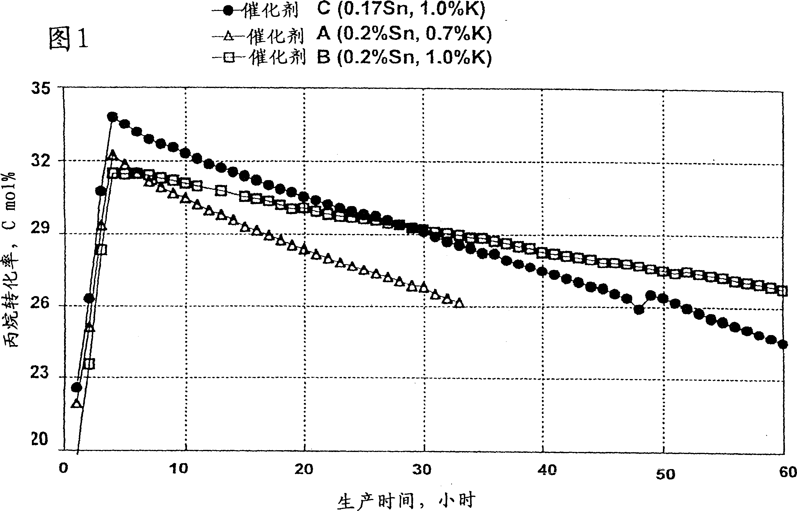
[0053] According to the present invention, the dehydrogenation reaction of hydrocarbons deactivates the deactivation catalyst during 100 hours of operation before it requires regeneration of the catalyst. Therefore, the activity of the dehydrogenation catalyst is graded by its initial maximum activity and its performance over a period of 5-20 hours on stream.

[0054] In order to demonstrate the advantages obtained with the present invention, a catalyst according to the invention and two prior art catalysts were prepared.

[0055] The first prior art catalyst contained 0.2 wt% tin and 0.7 wt% potassium and the second prior art catalyst contained 0.2 wt% tin and 1 wt% potassium. The catalyst of the invention contains 0.17% by weight tin and 1% by weight potassium. These catalysts are labeled Catalyst A, Catalyst B and Catalyst C, respectively. First, for all three catalysts, spherical alumina supports were prepared using the known oil drop method. The tin component is introd...


PUM


Abstract

A catalyst composite is disclosed. Also disclosed is its use for dehydrogenation reactions. The catalyst composite comprises a Group VIII noble metal component, a Group IA or IIA metal component, and a component selected from the group consisting of tin, germanium, lead, indium, gallium, thallium, or mixtures thereof, all on an alumina support comprising essentially theta-alumina, having a surface area from 50 to 120 m2 / g, an apparent bulk density of at 0.5g / cm3 and a mole ratio of the Group VIII noble metal component to the component selected from the group consisting of tin, germanium, lead, indium, gallium, thallium or mixtures thereof in the range from 1.5 to 1.7.

Description

technical field [0001] This invention relates to the conversion of hydrocarbons in the presence of catalyst compositions, and in particular to the dehydrogenation of dehydrogenatable hydrocarbons. The present invention also relates to a novel catalyst composition. Background technique [0002] Dehydrogenation of hydrocarbons is in great demand due to the production of various chemical products such as detergents, high-octane gasoline, pharmaceuticals, plastics, synthetic rubber and other products known to those skilled in the art, so dehydrogenation of hydrocarbons is a important industrial method. An example of such a process is the dehydrogenation of isobutane to produce isobutylene, which can be polymerized to provide tackifiers for adhesives, viscosity index additives for motor oils, impact resistance for plastics and Antioxidant additive and component for oligomeric gasoline. [0003] Various catalyst compositions are known in the prior art which contain a Group VIII...

Claims


Application Information

Patent Timeline
Patent Type & Authority Patents(China)
IPC IPC(8): B01J23/62B01J23/58C07C5/32B01J21/04B01J35/00B01J35/10B01J37/00B01J37/02C07B61/00C07C11/06
CPCB01J35/0026B01J23/62C07C5/325C07C2523/62B01J35/1019B01J23/626B01J21/04B01J35/002B01J35/1014B01J23/58B01J37/0207B01J37/0072Y02P20/52B01J35/613B01J35/615B01J35/32C07C5/32B01J35/30B01J35/31
Inventor T·V·沃斯科博尼克弗D·H·魏J·W·A·萨驰特勒B·V·沃拉
Owner UOP LLC
Learn More