Injector with throttle variable nozzle and injector circulation using such injector
A technology of injectors and throttle valves, which can be used in the direction of fluid circulation arrangements, irreversible circulation compressors, jet pumps, etc., and can solve problems such as damaging nozzle efficiency
- Summary
- Abstract
- Description
- Claims
- Application Information
AI Technical Summary
Problems solved by technology
Method used
Image
Examples
no. 1 example
[0025] The injector of the embodiment related to the present invention is generally used in the injector cycle of a vehicle air conditioner.
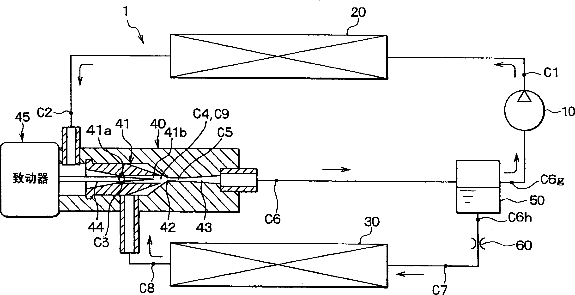
[0026] figure 1 A schematic diagram of an ejector cycle 1 using carbon dioxide as refrigerant is shown. The compressor 10 is a variable displacement compressor for sucking and compressing refrigerant, and is driven by a vehicle engine to operate. The discharge amount of the compressor 10 is controlled so that the temperature or pressure in the evaporator 30 (described later) is controlled within a predetermined range.
[0027] The radiator 20 is a high-pressure side heat exchanger that cools the refrigerant by performing heat exchange between the refrigerant discharged from the compressor 10 and the outside air (ie, the air outside the passenger compartment). The evaporator 30 is a low-pressure side heat exchanger that cools the air to be blown toward the passenger compartment while evaporating the liquid refrigerant by performing hea...
no. 2 example
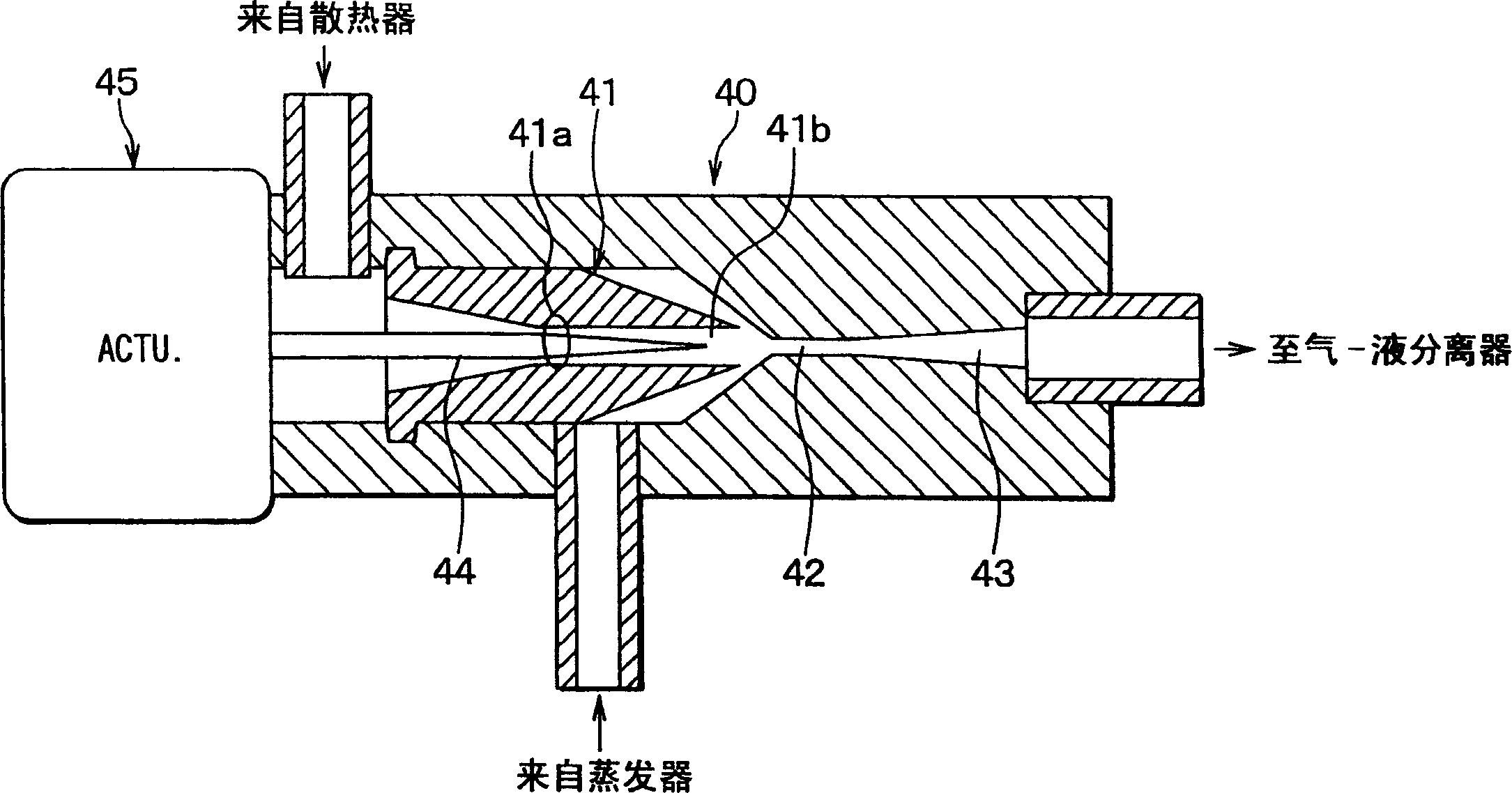
[0045] exist Figure 6 In the shown second embodiment, the shape of the inner wall of the throat 41a in the nozzle 41 according to the first embodiment is a curved surface, so that the cross-sectional area of the refrigerant passage changes continuously and smoothly from the refrigerant inlet of the nozzle 41 to the throat. 41a. In this way, generation of eddy currents in the downstream side near the throat portion 41a can be reduced, so that losses such as eddy current losses and the like can be reduced. As a result, nozzle efficiency can be further increased. In the second embodiment, other parts are similar to those of the first embodiment described above.
no. 3 example
[0047] In the above-described first embodiment of the present invention, the cross-sectional area of the refrigerant passage from the refrigerant inlet of the nozzle 41 to the throat 41a gradually decreases by a constant cone angle. However, in this example, if Figure 7 As shown, the cone angle θ1 on the throat 41 a side of the nozzle 41 is set smaller than the cone angle θ0 on the refrigerant inlet side of the nozzle 41 and the cone angle θ2 at the end of the needle valve 44 . In addition, the needle valve 44 controls the throttle opening degree from the minimum opening degree to the maximum opening degree, while at least the tip of the needle valve 44 is located on the downstream side of the throat portion 41a in the refrigerant flow.
[0048] In this embodiment, the cone angle θ1 of the throat 41a is smaller than the cone angle θ0 of the refrigerant inlet side of the nozzle 41, and the position of the throttle portion 41c is on the upstream side of the refrigerant flow r...
PUM
 Abstract
Description
Claims
Application Information
 - R&D
- Intellectual Property
- Life Sciences
- Materials
- Tech Scout
- Unparalleled Data Quality
- Higher Quality Content
- 60% Fewer Hallucinations
Browse by: Latest US Patents, China's latest patents, Technical Efficacy Thesaurus, Application Domain, Technology Topic, Popular Technical Reports.
© 2025 PatSnap. All rights reserved.Legal|Privacy policy|Modern Slavery Act Transparency Statement|Sitemap|About US| Contact US: help@patsnap.com


