Colour image sensor and driving method thereof

A color image and sensor technology, applied in color TV, color TV parts, instruments, etc., can solve problems such as low image resolution

Inactive Publication Date: 2006-08-02
RENESAS ELECTRONICS CORP
View PDF2 Cites 0 Cited by
  • Summary
  • Abstract
  • Description
  • Claims
  • Application Information

AI Technical Summary

Problems solved by technology

[0007] Also, even if the density of the light receiving portion is high, there is a case where the resolution of the reproduced image becomes lower depending on the user's usage environment

Method used


Image

  • Colour image sensor and driving method thereof
  • Colour image sensor and driving method thereof
  • Colour image sensor and driving method thereof

Examples


no. 1 example

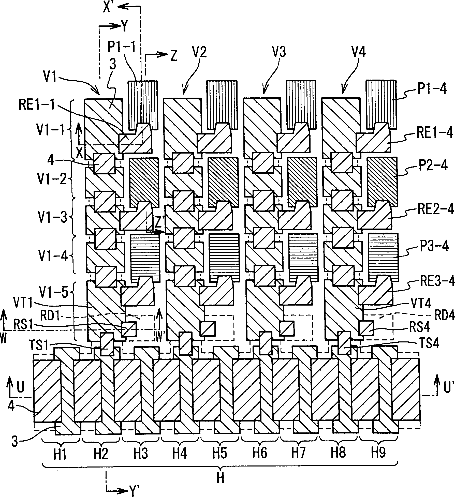
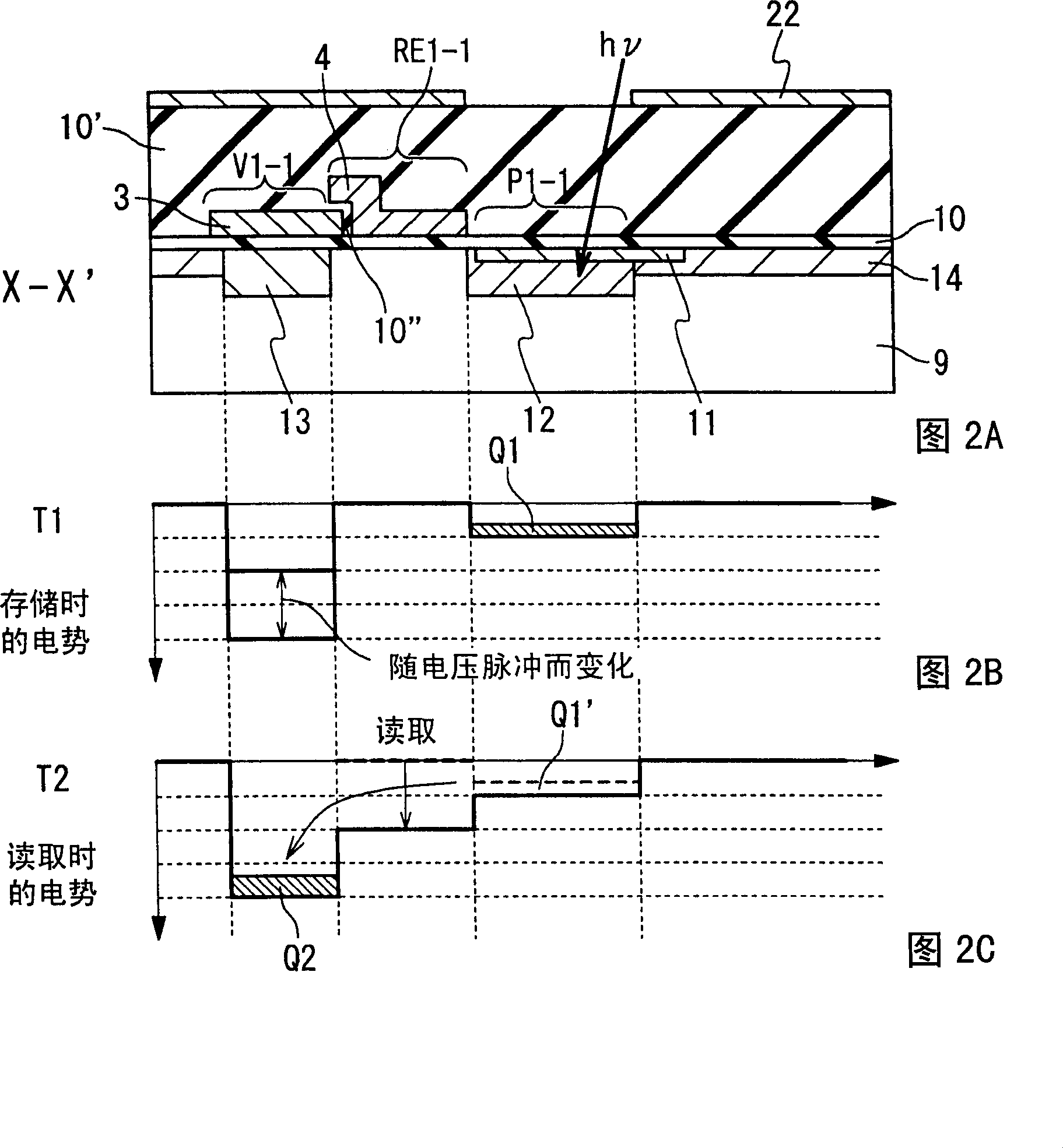
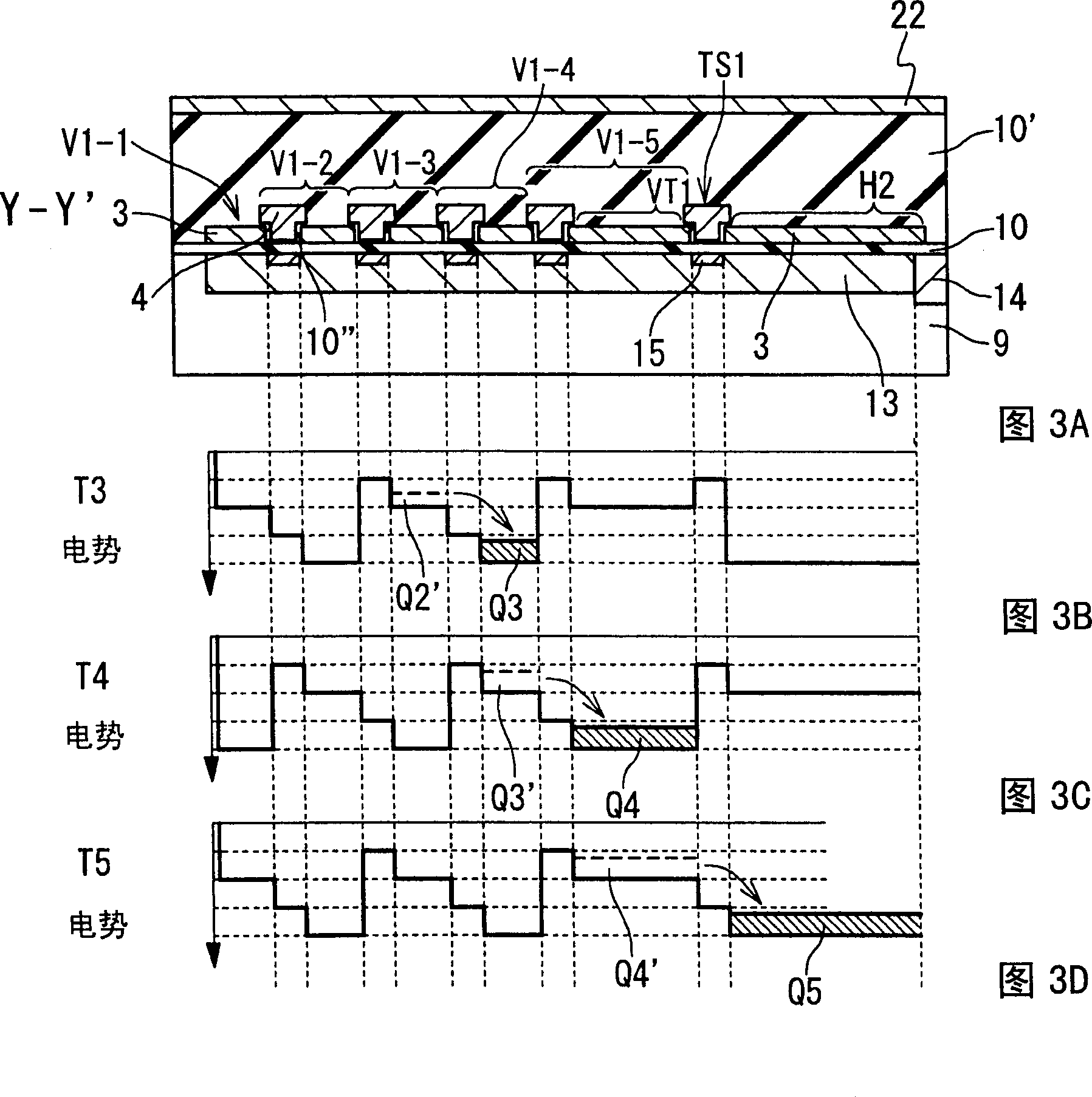
[0056] The following will refer to figure 1 The structure of the color image sensor according to the first embodiment of the present invention will be described. figure 1 A plan view showing the structure of the color image sensor according to the first embodiment of the present invention. The color image sensor includes: pixels P1-1 to P3-4, read gates RE1-1 to RE3-4, vertical scan charge transfer sections V1 to V4, horizontal scan charge transfer sections H, reset gates RS1 to RS4 , reset drains RD1 to RD4, and transfer switch sections TS1 to TS4. The color image sensor in the first embodiment is formed on a P-type substrate. However, the present invention can also be realized by forming a P-type well on an N-type substrate.

[0057] Here, in the description of the drawings of the present application, a wiring structure to each gate electrode, a via hole in a wiring connection portion, and a color filter are omitted. In addition, a metal thin film 22 for light shielding ...

no. 2 example

[0152] The following will refer to Figure 8 A color image sensor according to a second embodiment of the present invention will be described. Figure 8 A plan view showing the structure of a color image sensor according to a second embodiment of the present invention. The color image sensor includes: the first row of pixels P1-1 to P1-4 to the third row of pixels P3-1 to P3-4; the read gate RE1- corresponding to the pixels P1-1 to P3-4 1 to RE3-4; storage gates V1 to V4 as vertical scan charge transfer section H; reset drain RDi and transfer switch TSi. The color image sensor in this embodiment is formed on a P-type substrate.

[0153] The difference between this embodiment and the first embodiment is that the vertical scanning charge transfer sections V1 to V4 having a plurality of vertical scanning charge-coupled units are used in the first embodiment, while a single storage Grid 19. By using a single storage gate, the voltage pulse φ for multiple vertical scanning char...


PUM


Abstract

A color image sensor includes a plurality of image elements, a plurality of read gate sections, a plurality of vertical scanning charge transfer sections, and a plurality of transfer switch sections. The plurality of image elements are arranged in a matrix of rows and columns and each of the plurality of image elements generates an electric charge in response to incidence of light. The plurality of read gate sections are provided for the plurality of image elements, and each of the plurality of image elements controls transfer of the electric charge generated in a corresponding one of the plurality of image elements. Each of the plurality of vertical scanning charge transfer sections is provided for every column of the matrix to hold and transfer the electric charges transferred from a corresponding column of the plurality of read gate sections. Each of the plurality of transfer switch sections is provided for a termination section of a corresponding one of the plurality of vertical scanning charge transfer sections to control transfer of the electric charges from the corresponding vertical scanning charge transfer section. The horizontal scanning charge transfer section is provided for the plurality of transfer switch sections to hold and transfer the electric charges transferred from the plurality of vertical scanning charge transfer sections via the plurality of transfer switch sections.

Description

technical field [0001] The present invention relates to a color image sensor for converting a color image into an electric signal, and a method of driving the color image sensor. Background technique [0002] When using a charge transfer device having a one-dimensional charge-coupled cell, the read operation of a two-dimensional color image is performed as follows. First, white light is irradiated onto the printed image, and then the reflected or transmitted light is decomposed into red (R), green (G) and blue (B) three-color light. Next, the light of each color is received by the light-receiving portion of the one-dimensional charge-coupled unit, and converted into charges according to the amount of light. Next, the charge is transferred by the charge transfer portion, and the charge is converted into an electric signal by the charge-voltage converter provided at the end of the charge transfer portion. The electrical signal is then stored in memory. After this, the charg...

Claims


Application Information

Patent Timeline
Patent Type & Authority Patents(China)
IPC IPC(8): H01L27/148H01L29/762H01L21/339H04N5/335H04N5/225G03F3/08H04N5/357H04N5/369H04N5/372
CPCH04N5/37213H01L27/14831H01L27/14868H04N5/361H04N5/3692H04N25/701H04N25/63H04N25/713
Inventor 纲井史郎
Owner RENESAS ELECTRONICS CORP
Why Eureka
Try Eureka